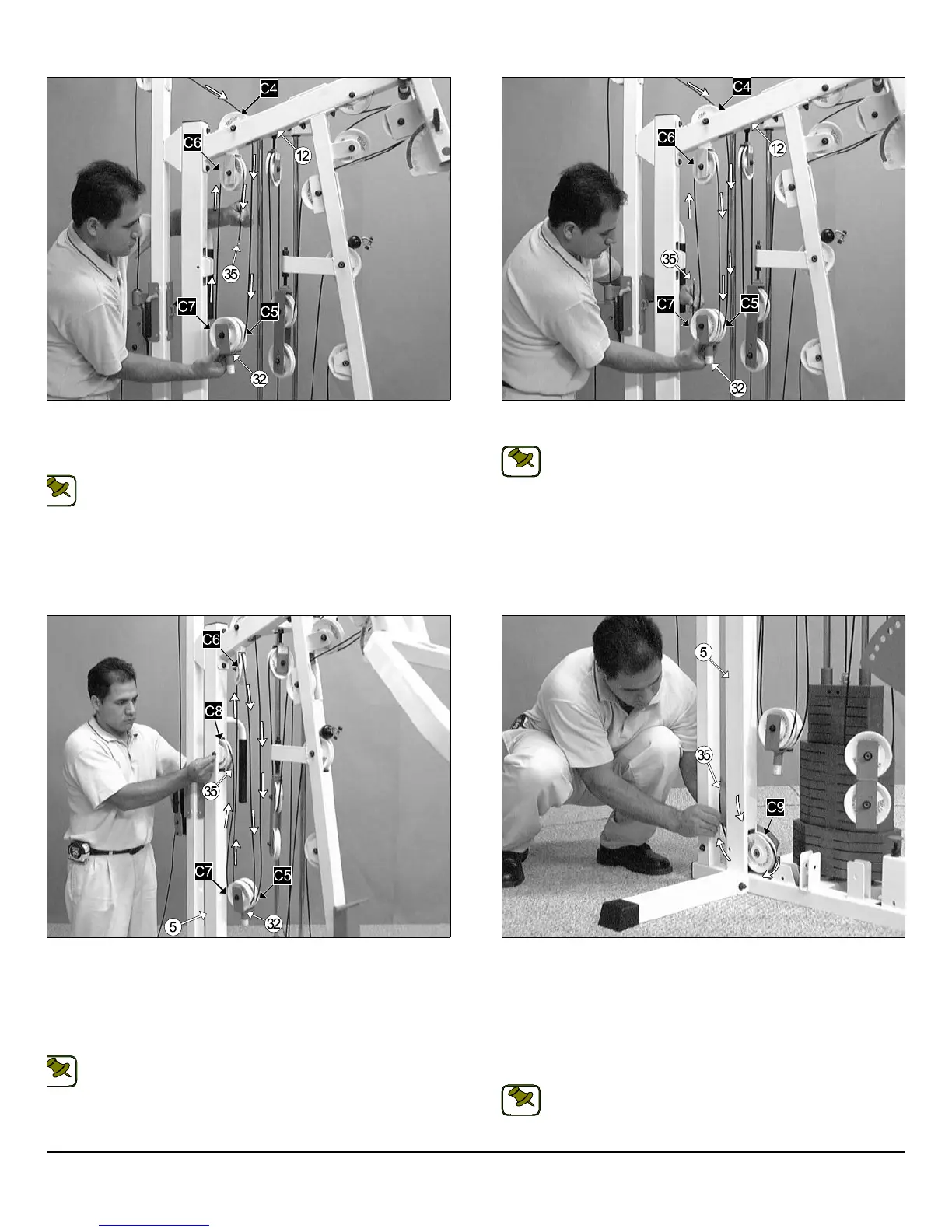
IG. 58 Next, route the High-Low Cable (#35) down into the tube of
e Rear Upright (#5). Next, insert a Nylon Pulley 4 1/2 Rd. (#67-Labeled
8) into the slot of the Rear Upright (#5) and secure it into place using
ne Hex Head Cap Screw 3/8-16 X 2 1/2 (#101), two Flat Washers SAE
8” (#87), and one Nylon Insert Jam Lock Nut 3/8-16 (#93). Be sure the
ble is routed properly into the groove on the Nylon Pulley 4 1/2 Rd.
67-Labeled C8).
Note: Refer to the Cable Mapping Diagram on page 26 for further
detailed illustration of the High-Low Cable (#35) routing.
FIG. 59 Continue routing the High-Low Cable (#35) down into the tu
of the Rear Upright (#5). Next, pull the Cable end through the opening
the bottom of the Rear Upright (#5). Then, route the cable around
Nylon Pulley 4 1/2 Rd. (#67-Labeled C9), as shown above. Secure th
Nylon Pulley 4 1/2 Rd. (#67-Labeled C9) to the Rear Upright (#5) usin
one Hex Head Cap Screw 3/8-16 X 2 1/2 (#101), two Flat Washers SA
3/8” (#87), and one Nylon Insert Jam Lock Nut 3/8-16 (#93). Be sure th
cable is routed properly into the groove on the Nylon Pulley 4 1/2 R
(#67-Labeled C9).
Note: Refer to the Cable Mapping Diagram on page 26 for furth
detailed illustration of the High-Low Cable (#35) routing.
IG. 56 Next, locate the Floating Double Pulley Bracket (#32) and
ntinue to route the High-Low Cable (#35) down and under the Nylon
ulley 4 1/2 Rd. (#67-Labeled C5). Then, up and over the Nylon Pulley 4
2” Rd. (#67-Labeled C6).
Note: Refer to the Cable Mapping Diagram on page 26 for further
detailed illustration of the High-Low Cable (#35) routing.
FIG. 57 Next, route the High-Low Cable (#35) down and under the N
lon Pulley 4 1/2 Rd. (#67-Labeled C7).
Note: Refer to the Cable Mapping Diagram on page 26 for furth
detailed illustration of the High-Low Cable (#35) routing.
S-1000 Home Gym w/Adjustable High-Low Pulley System 16
wner
s
anua
:
ssem
y
nstruct
on
OTE:
NOTE:
NOTE:
NOTE: