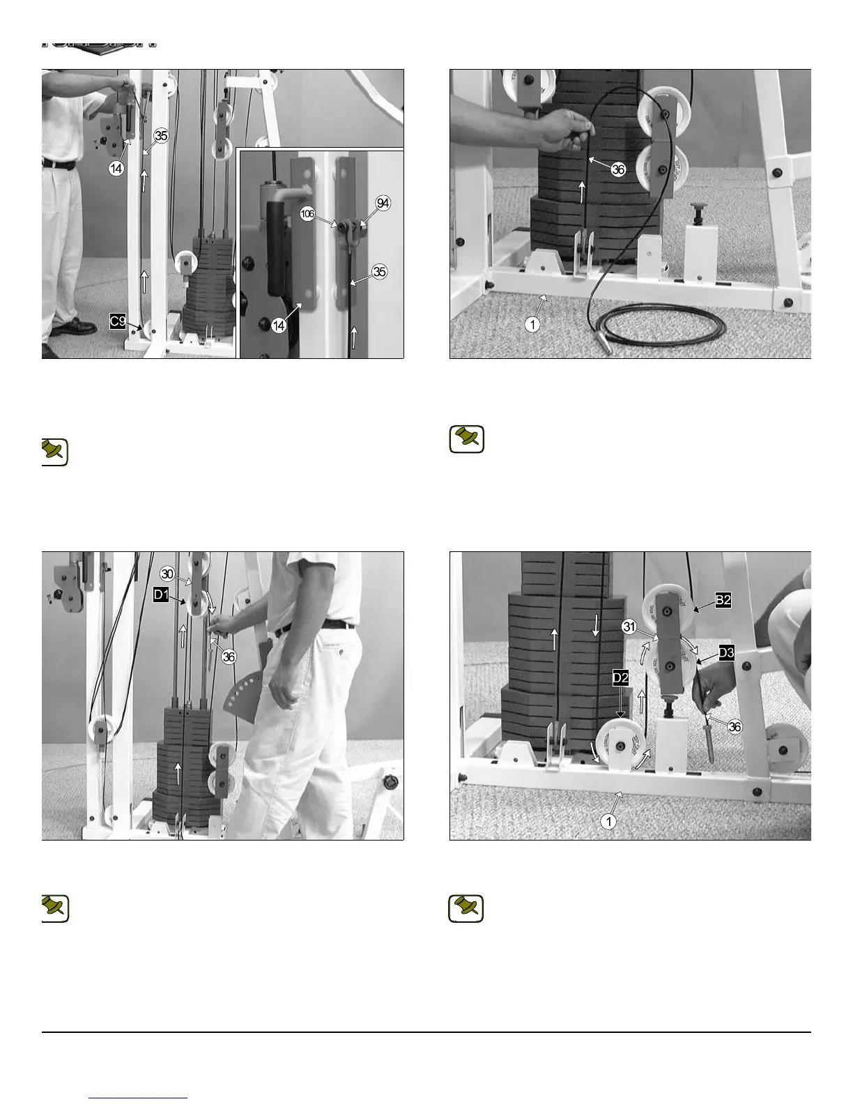
IG. 62 Route the Tension Cable (#36) up to the Closed-End Adj.
ouble Pulley Bracket (#30) and over the Nylon Pulley 4 1/2 Rd (#67-
beled D1), as shown above.
Note: Refer to the Cable Mapping Diagram on page 27 for further
detailed illustration of the Tension Cable (#36) routing.
FIG. 63 Continue routing the Tension Cable (#36) down and under th
Nylon Pulley 4 1/2 Rd (#67-Labeled D2). Then, up and over the Nyl
Pulley 4 1/2 Rd (#67-Labeled D3).
Note: Refer to the Cable Mapping Diagram on page 27 for furth
detailed illustration of the Tension Cable (#36) routing.
IG. 60 Next, route the High-Low Cable (#35) up to the High-Low Car-
age (#14) and insert the cable to the welded bracket on the side of the
igh-Low Carriage (#14), as shown in caption above. Lock the High-
ow Cable (#35) into place using one Shoulder Bolt 3/8 x 3/4 (#106), and
ne Nylon Insert Lock Nut 5/16-18 (#94).
Note: Refer to the Cable Mapping Diagram on page 26 for further
detailed illustration of the High-Low Cable (#35) routing.
FIG. 61 Affix the looped end of the Tension Cable (#36) to the pull
bracket located on the Base Frame (#1) using one Hex Head Cap Scre
3/8-16 x 1 3/4 (#102), two Flat Washers SAE 3/8” (#87), two Nylon spa
ers 3/8 x 3/8 (#109), and one Nylon Insert Jam Lock Nut 3/8-16 (#93).
Note: Refer to Fig F on page 27 for further illustration of this a
sembly.
17
TS-1000 Home Gym w/Adjustable High-Low Pulley Syste
OTE:
NOTE:
NOTE:
NOTE: