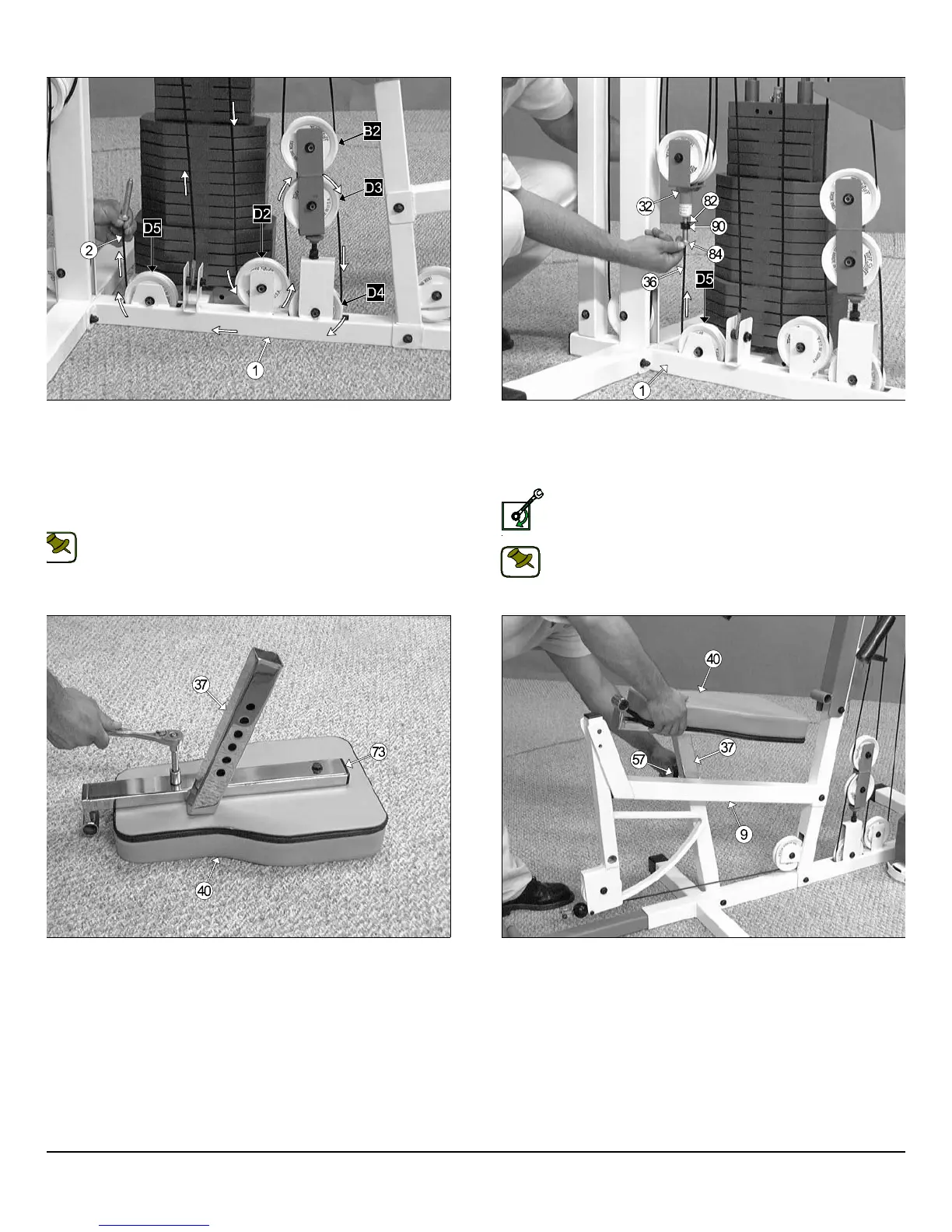
IG. 66 Next, using a rubber mallet, insert a Plastic Insert Cap 1 X 2
73) into the tube-end of the Adjustable Seat Frame (#37). Next, locate
e Seat Pad (#40) and attach it to the Adjustable Seat Frame (#37), as
own above, using two Hex Head Cap Screws 3/8-16 X 1 3/4 (#102),
nd two Flat Washers SAE 3/8” (#87).
FIG. 66 Insert the assembled Adjustable Seat Frame (#37) into th
Leg Extension Bench Frame (#9), in the position as shown above. B
sure to release the Turn/Pull Pin w/Knob (#557) as you begin inserting th
assembled Adjustable Seat Frame (#37) into the Leg Extension Benc
Frame (#9).
IG. 64 Route the Tension Cable (#36) into the tube of Base Frame
1) then pull it out through the opening at the top of the Base Frame
1). Next, insert two Nylon Pulleys 4 1/2 Rd (#67-Labeled D4, D5) to the
ulley brackets located on the Base Frame (#1) and secure them into
lace using two Hex Head Cap Screws 3/8-16 x 1 3/4 (#102), four Flat
ashers SAE 3/8” (#87), and two Nylon Insert Jam Lock Nuts 3/8-16
93). Be sure the cable is routed properly into the grooves of the Nylon
ulleys 4 1/2 Rd. (#67-Labeled D4, D5), as shown above.
Note: Refer to the Cable Mapping Diagram on page 27 for further
detailed illustration of the Tension Cable (#36) routing.
FIG. 65 Conclude the routing of the Tension Cable (#36) by Threa
ing a Regular Hex Nut 1/2-13 (#90) and inserting a Split Washer B/
1/2” (#82) to the Hex Tap Bolt 1/2-13 x 3 (#84). Then, thread the Hex T
Bolt 1/2-13 x 3 (#84) to the threaded socket located on the Floating Do
ble Pulley Bracket (#32).
Loosely Fasten: Do not completely fasten this hardware asse
bly at this time, as it will be completely fastened later in the a
sembly process.
Note: Refer to the Cable Mapping Diagram on page 27 for furth
detailed illustration of the Tension Cable (#36) routing.
S-1000 Home Gym w/Adjustable High-Low Pulley System 18
wner
s
anua
:
ssem
y
nstruct
on
NOTE:
NOTE: