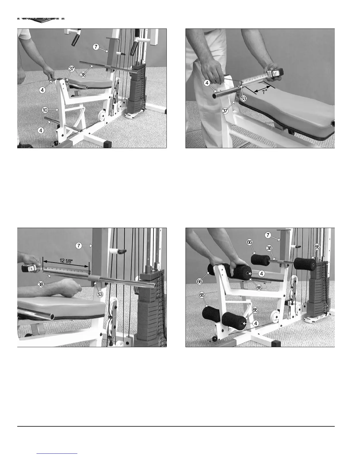
IG. 70 Use a measuring tape to center the Foot Roll Tube 1 x 27
38) with the Adjustable Back Pad Bracket’s (#7) receptacle. The
easurement from one end of the tube to the receptacle, as pictured
bove, should be about 12 1/8”. Secure the Foot Roll Tube 1 X 27 (#38)
the Adjustable Back Pad Bracket (#7) using a Set Screw 1/4-20 X 1/4
53), as shown above. Use the supplied Hex Key 1/8” (#115) to properly
cure the Set Screw 1/4-20 X 1/4 (#53) into place.
FIG. 71 Next, attach one Foam Foot Roll 7 X 4 X 1 (#62) to each en
of the three tubes as shown above. Refer to the Exploded View Diagra
on fold out page for further clarification of this assembly.
IG. 68 Next, insert a Foot Roll Tube 1 X 16 (#4) into the receptacle
the Adjustable Seat Frame (#37). Then, insert another Foot Roll
ube 1 X 16 (#34) into the receptacle of the Leg Extension Arm (#10).
ext, insert the Foot Roll Tube 1 X 27 (#38) into the receptacle of the
djustable Back Pad Bracket (#7), as shown above.
FIG. 69 Use a measuring tape to center the Foot Roll tube 1 x 16 (#
with the Adjustable Seat Frame’s (#37) receptacle. The measureme
from one end of the tube to the receptacle, as picture above, should
about 7”. Secure the Foot Roll Tube 1 X 16 (#4) to the Adjustable Se
Frame (#37) using a Set Screw 1/4-20 X 1/4 (#53), as shown above. Us
the supplied Hex Key 1/8” (#115) to properly secure the Set Screw 1/4-2
X 1/4 (#53) into place.
19
TS-1000 Home Gym w/Adjustable High-Low Pulley Syste