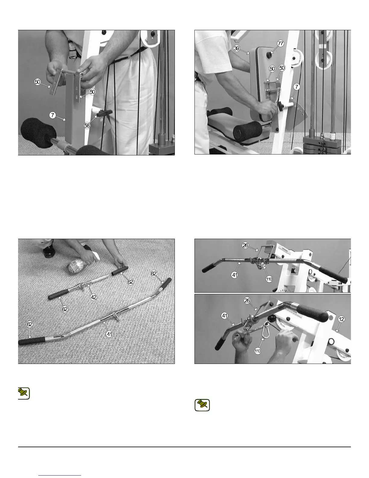
IG. 59 Attach two Metal Hinges (#50) to the axle of the Adjustable
ack Pad Bracket (#7). Be sure to position the Metal Hinges (#50) as
own above.
FIG. 60 Next, attach the Back Pad (#39) to the Metal Hinges (#50),
shown above, and secure them into place (at the top hole of the Met
Hinge) using two Hex Head Cap Screws 3/8-16 X 1 1/4 (#103), and tw
Flat Washers SAE 3/8” (#87).
IG. 61 Insert a Rubber Grip 1 x 6 1/4 (#62) over each one of the tube-
nds of the Low Row Bar 20” (#42), and the Lat Bar 48” (#41), as shown
bove.
Note: To facilitate the insertion of these Rubber Grips, use Windex
or household glass cleaner.
FIG. 62 Next, attach a Snap Link (#110) to the Lat Cable (#33), in th
position as shown above, and secure it into place using one Shoulder B
3/8 x 3/4 (#106), and one Nylon Insert Lock Nut 5/16-18 (#94). Use th
supplied Hex Key 3/16” (#114) and a 1/2” combination wrench to faste
this assembly properly.
Note: Refer to Fig. A on page 24 for further illustration of this a
sembly.
Connect the Lat Bar 48” (#41) to the Lat Cable (#33) using the Snap Li
(#110). Use the Lat Bar Holder (#26) to rest the Lat Bar 48” (#41) ont
when not in use
20
S-1000 Home Gym w/Adjustable High-Low Pulley System
wner
s
anua
:
ssem
y
nstruct
on
NOTE:
NOTE: