EasyManua.ls Logo

TUR Isoforce - Dynamometer Assembly; Dynamometer Rotation

TUR Isoforce
77 pages
Print Icon
To Next Page IconTo Next Page
To Previous Page IconTo Previous Page
Loading...
5.2.1 User Manual Isoforce
REV 5 01st July 2014 page 16 von 77
TUR Therapietechnik GmbH | Grubenstr. 20 | 18055 Rostock | Germany
2.1 Dynamometer Assembly
You can easily and comfortably make the following dynamometer’s translations.
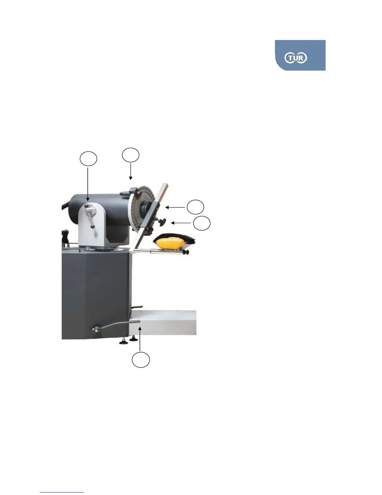
2.1.1.Dynamometer Rotation
You can rotate the dynamometer in the horizontal plane, both clockwise and counter-clockwise. In order
to do so, just lightly step on the dynamometer release pedals, DR pedals. While pressing them you can
rotate the dynamometer either directions. On the rotation scale, which is placed under the
dynamometer yoke, and around the vertical tube, you can read the dynamometer’s position.
1
Dynamometer Release pedals (DR)
2
Input adaptor tube
3
Adaptors’ knob
4
Range of motion mechanical stops
5
Dynamometer Tilt Level (DT)
1
2
3
5
Pic 2.1 Dynamometer Assembly

Table of Contents