Service Differences
Detailed servicing instructions are provided in the HhB and
HhB 2 ser
vice manuals.
Notable Part Location Changes
The smar
t card reader, high-limit thermostat, rack motor,
and fuses w
er
e relocated for easier serviceability and/or more
efficient oven operation/installation (Figures 4-12).
M
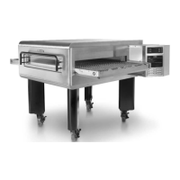
ultiple Fuse Configurations
The fuses on the original HhB oven were located on the back
panel.
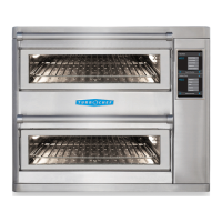
The HhB 2 oven fuses are located on a fuse block
behind the right-side panel and can be field-configur
ed for
single or multiphase operation. See Figures 7 and 8, below.
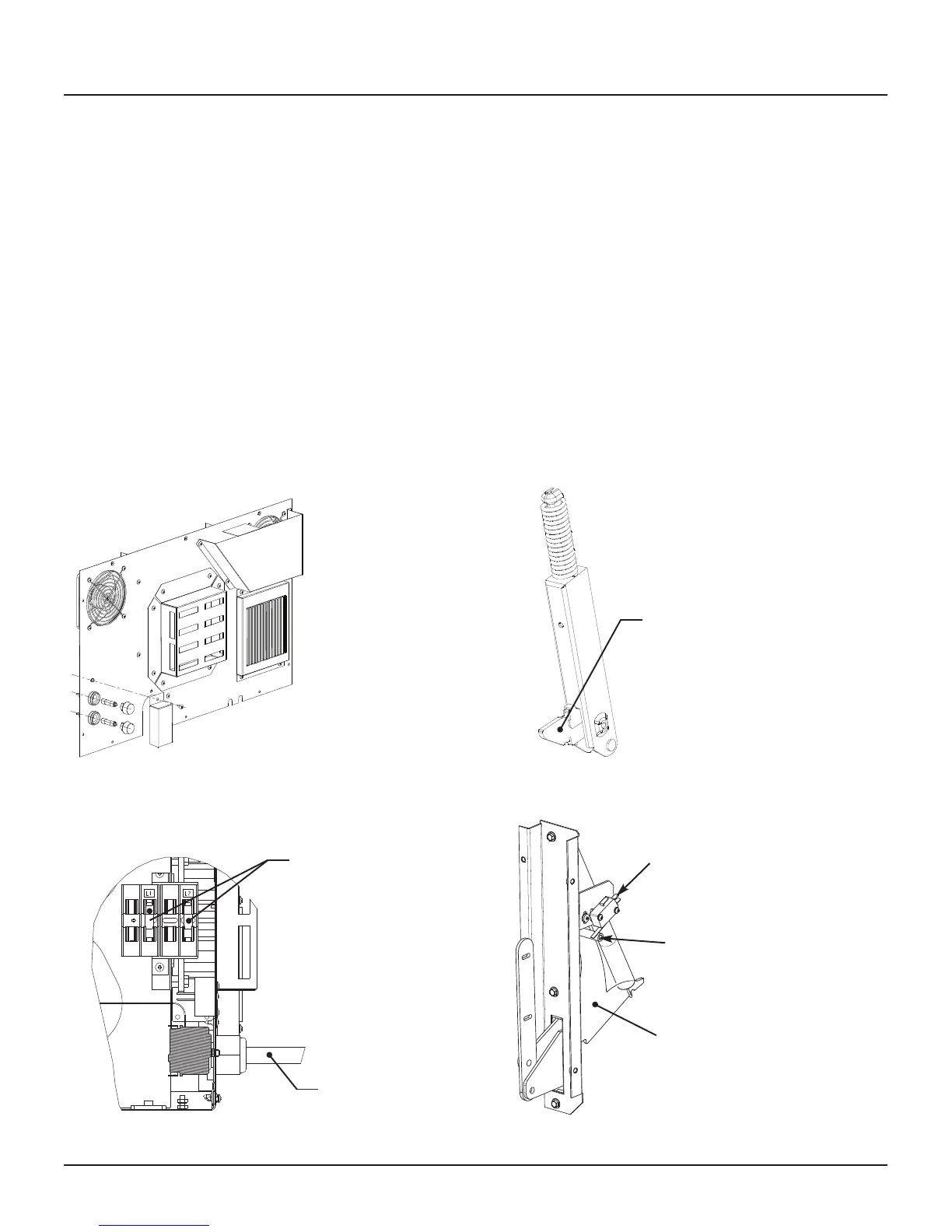
Door Hinges
The hinges on the original HhB o
ven were secured to the
o
v
en door, allowing for door removal during deep cleaning.
The hinges on the HhB 2 oven are secured to the oven
frame, and the right-side hinge actuates the door switch for
improved reliability. See Figures 9 and 10, below.
D
oor Switch
The door switch on the original HhB o
v
en was either a
magnet or plunger-style switch, depending on the date of
manufactur
e. The original HhB switch (regardless of type)
was actuated b
y the door itself. The door switch on the HhB
2 is a paddle-style switch that is actuated b
y the right-side
hinge, impr
oving the detection of the door position. See
Figure 10, below.
F
igure 9: Original HhB Hinge
F
igur
e 10: HhB 2 Hinge and Switch
P
addle-style switch
Switch actuated
b
y hinge
Hooks into frame
DOC-1201 (
A
) / Page 3 of 5
F
igure 7: Original HhB Fuse Location
Figure 8: HhB 2 Fuse Location
Power cord
Fuses in positions 2
and 4 f
or single
phase operation.
Not
e: Fuses are
mo
ved to positions 3
and 4 for multiphase
Wye, and to positions
1 and 2 for multi-
phase D
elta.
Hinge assembly
HhB/HhB 2 Comparison Outline
 Loading...