27
SUPPLY VOLTAGE
ENTER
VIN OK
ENTER
Input Power Supply Verification: the reading on the display should be between 22V and 37V. If
the message ‘VIN FAIL’ appears the mains voltage is outside the correct range (refer to
‘Specifications’ section): change to a more suitable power supply source. Otherwise, replace the
power supply adapter.
SECURITY LEVEL
ENTER
Press arrows to Select
ENTER
<check>
ENTER
Selection of the Security Level: the current IS or LD setting is displayed. Change it , if
necessary (refer to the FAT report provided with the equipment).
CHANNEL SELECT.
ENTER
Selection of the Operating Channel:
AutoCS ? Y
ENTER
< channel search>
ENTER
to perform an automatic search in case of a
single installation (no other MDs within a range of 15m).
AutoCS ? N
ENTER
CH
ENTER
to set the operating channel (CH) manually, in case of
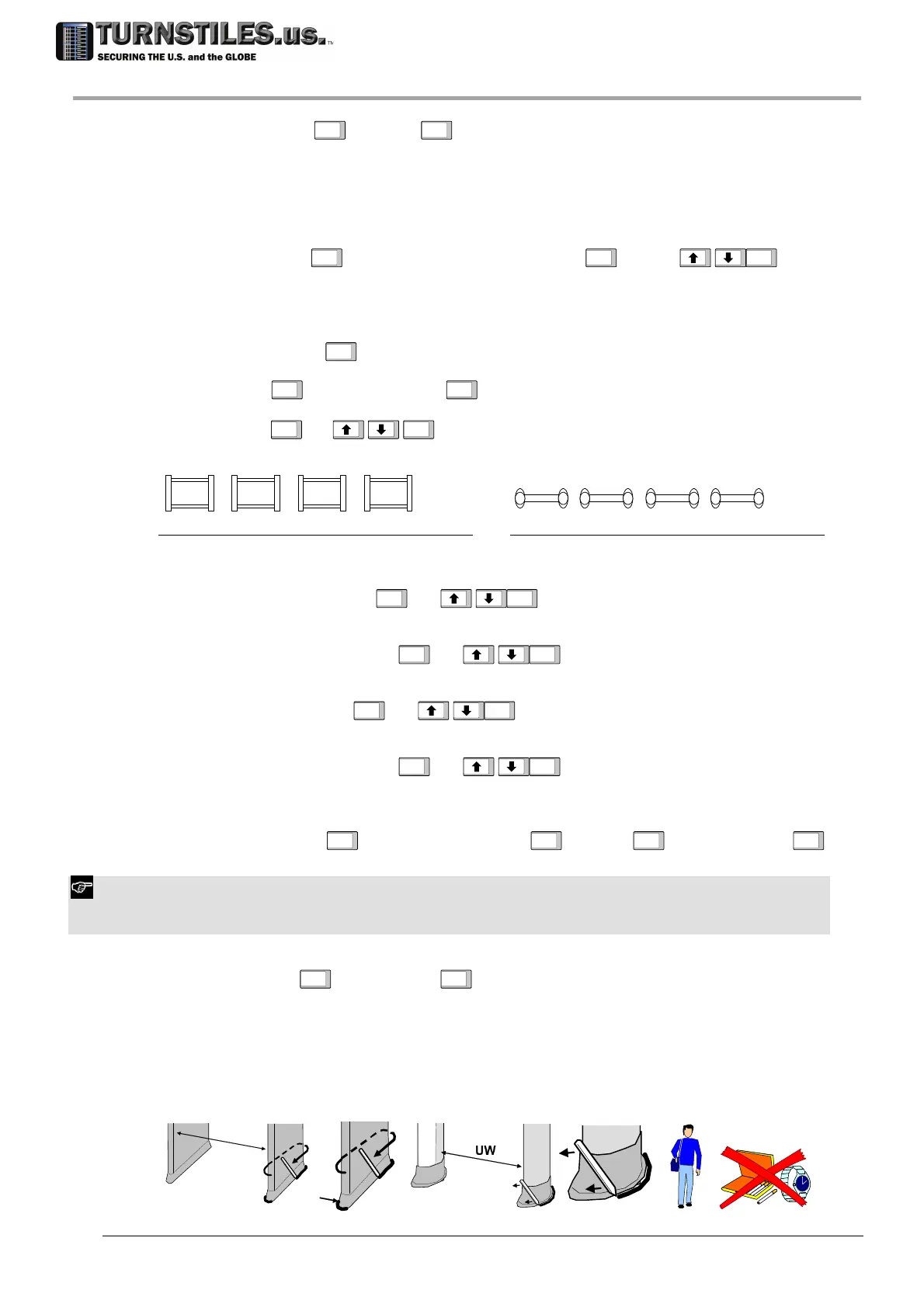
a multiple installation. Setting of CH parameter for up to 4 MDs:
TX RX RX TX TX RX
CH=1 CH=2 CH=3
CH=51 CH=52 CH=53
50 Hz
60 Hz
…
CH=4
CH=54
RX TX
mains
CH=1 CH=2 CH=3
CH=51 CH=52 CH=53
50 Hz
60 Hz
…
CH=4
CH=54
TX RX RX TX TX RX RX TX
mains
ALARM VOLUME SELECT.
ENTER
AV
ENTER
Selection of the Alarm Volume.
MINIMUM VOLUME SELECT.
ENTER
MV
ENTER
Selection of the Minimum Volume (lower limit for alarm volume adjustment).
ALARM TONE SELECT.
ENTER
AT
ENTER
Selection of the Alarm Tone.
ALARM DURATION SELECT.
ENTER
AD
ENTER
Selection of the Alarm Duration.
GATE DIR SELECT.
ENTER
Transit inbound
ENTER
GD=1 Y
ENTER
<inbound transit>
ENTER
Selection of the Transit Direction: pass through the gate along the desired inbound direction.
To repeat the step, change ‘Y’ to ‘N’, using the arrow keys and press ENTER key to confirm.
In case photocells are not installed set GD parameter to enable the pacing lights on the outbound (unsecure) side of the
archway.
FLOOR ADJUST.
ENTER
Run FGA?Y
ENTER
<FGA procedure > FGA OK
FGA Adjustment of Gain at ground level (this step requires the FGA-TFV kit be available).
Ensure that the passage width (UW in the figure below) of the gate is correct (refer to the
‘Specifications’ section).
Mark the position of the archway on the floor (for instance by tracing the outline of the panels
with a felt-tip pen).
The operator must carry out the test without wearing any metal objects!
The test procedure is detailed in the instructions included in the FGA kit.
UW
303-670-1099