15
3.3.2 Assembly Procedure of the Panel-Shape Version
PSA
vt
AW1
AW2
ck
K
cf
vc
cbc
vc
cbc
TX1
IK
cp
ccp
PC
cmp
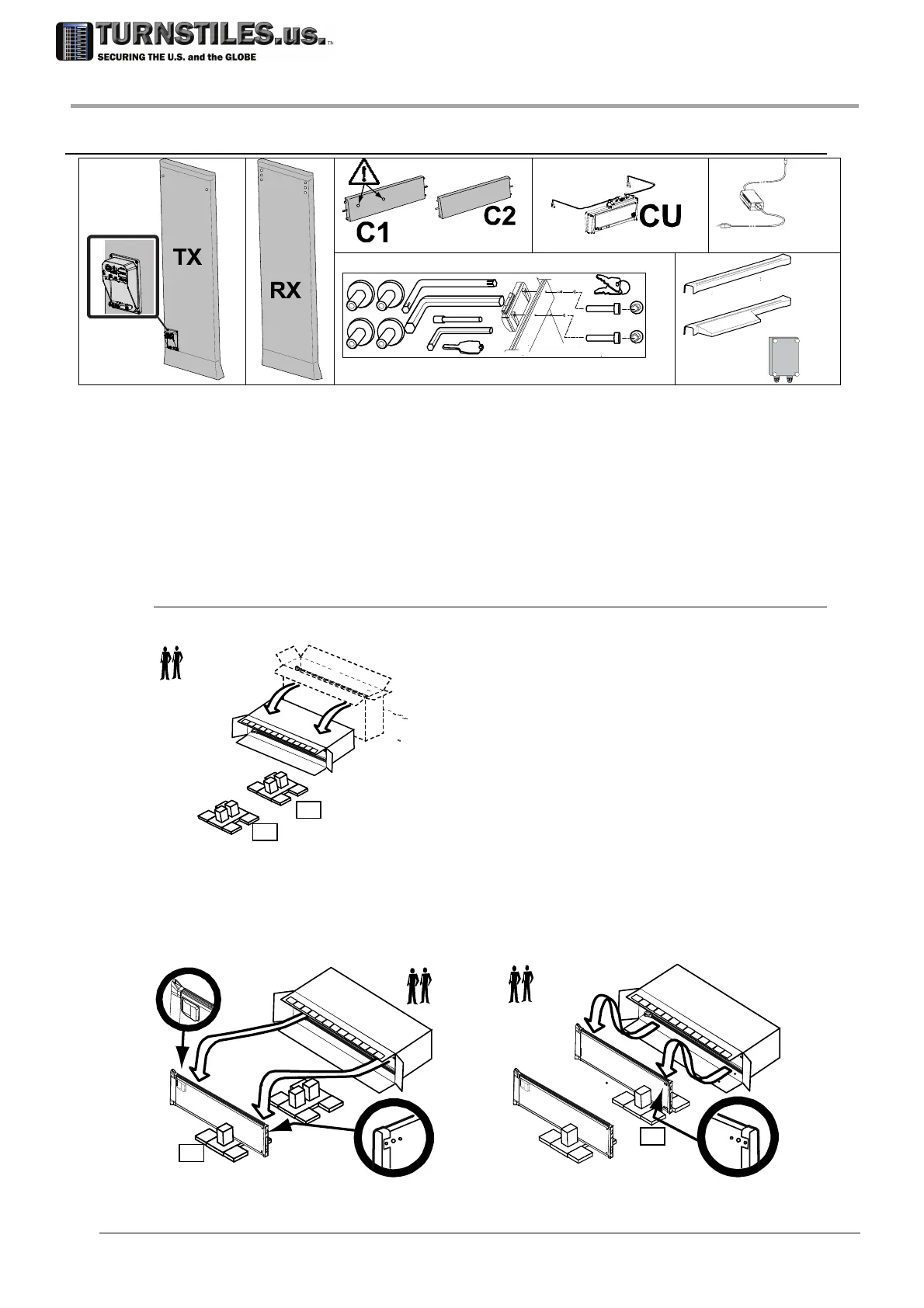
TX
TX antenna
RX
RX antenna
C1
Crossbar fitted with holes for
mounting the control unit
C2
Crossbar without holes
CU
Control unit
PSA
AC/DC power supply adapter
IK
Installation kit:
AW1
Allen wrench for crossbar
AW2
Allen wrench for control unit
cbc
cap for crossbar fixing holes
cf
key of control unit lock
ck
screwdriver for upper connectors
K
on/off key
vc
control unit mounting screw
vt
crossbar fixing screw
PC
Protection covers:
cmp
protection cover of the
lower connection
module
ccp
protection cover of CU
control unit and C1
crossbar
cp
protection cover of C2
crossbar
Pictures of main components
Positioning the panels
Tilt down the packaging containing the archway panels.
Place S1 and S2 spacers on the floor as illustrated in the figure below.
Extract the upper panel (TX) from the packaging and place it on the S1 spacer, making sure that
its internal side is facing the packaging .The internal side of each panel is identified by the three
holes in the cross-bar mounting area (detail D1).
Extract the lower panel (RX) from the packaging and place it on the S2 spacer, making sure that
its internal side is facing the other panel (detail D2).
TX
D1
TX
RX
D2
S2
S1
S1
S2
303-670-1099