13
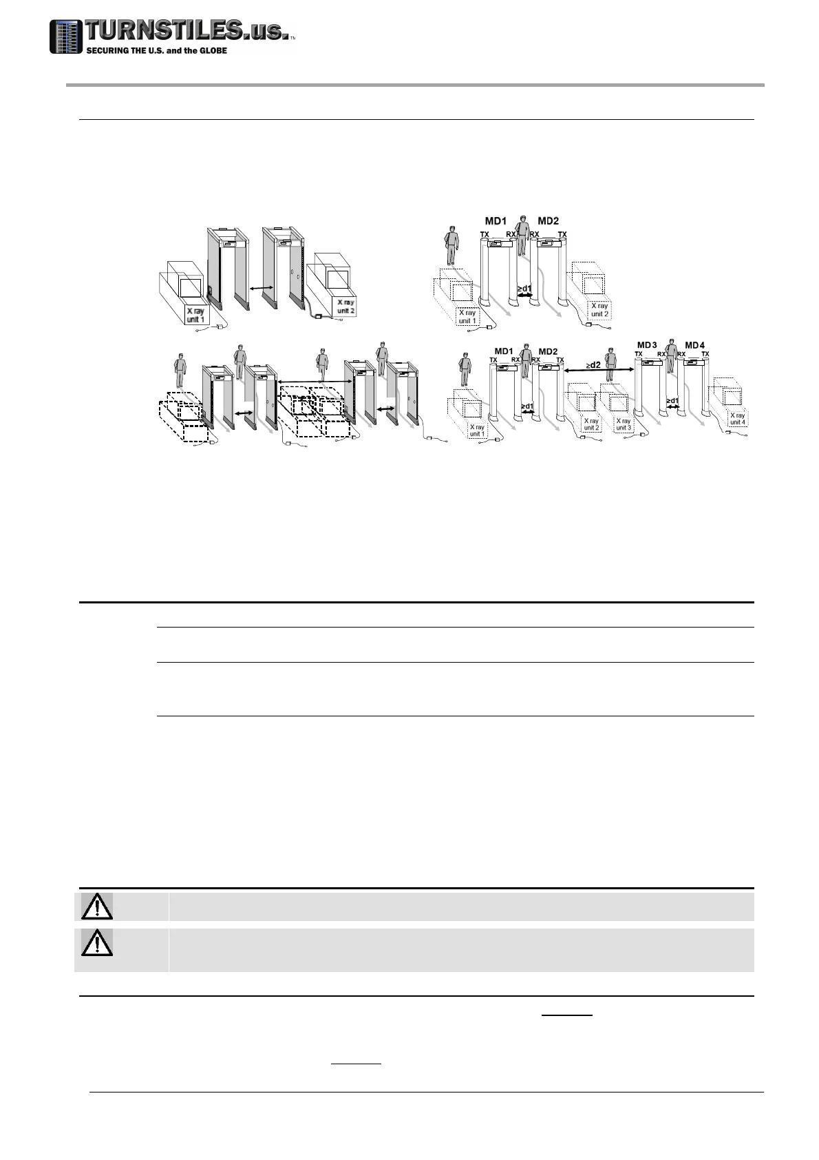
3.1.2 Multiple installation
In case of the installation of multiple units it is necessary to respect the following rules, in order to
synchronize each unit with the other ones.
Place the MDs following the sequence: TX-RX - RX-TX - TX-RX ...
Ensure that the distances (‘d1’ and ‘d2’ in the figure below) between the MDs are not less
than the minimum required.
Xray
unit 1
Xray
unit 2
>d1
RX RX TXTX
d1 = 5cm
MD4
Xray
unit 3
MD3
RXTX
RX
TX
Xray
unit 1
MD1
RX
TX
Xray
unit 2
MD2
RX
TX
>d1
>d1
>d2
d1 = 15cm, d2 =100 cm
Enter programming and set a different channel (CH) on each MD, according to its position
(this can be performed during the OTS procedure, see the following steps).
3.2 Installation procedure overview
Personnel needed
Two qualified installers or more and one authorised Security Representative
Knowledge required
Some MD working parameters: refer to the ‘Programming’ section
Operating requirements established by the Security Authority
Components needed
Unpacking: Scissors and Pliers
Phillips screwdriver n.1
Kit C.E.I.A. FGA & TFV ()
Metal-free clothes (Clean Tester): Tracksuit, Gym shoes, No metal personal effects (metal cases, metal
watch, …)
Anchoring to the floor by means of screws: drill, ratchet tightener (socket wrench) , expansion anchor
with Nr. 12-24 (or M6) screw
Tools for Verification of the Calibration (reference test pieces, …)
3.3 Assembly
Please note that Turnstiles.us is not responsible for any damage that may result from installations
that do not follow these guidelines.
Holes
It is strictly
forbidden to make holes in the Metal Detector antenna or to insert screws in
positions, or of lengths, not expressly indicated by Turnstiles.us. Damage due to such actions is not
covered by the product warranty.
3.3.1 Assembly rules
The control unit CU has to be mounted on the crossbar on the exit side of the gate, as it provides
the screener with the alarm signals.
The crossbar C1, fitted with holes for mounting the control unit CU, must be placed so that the
control unit is located on the exit side of the gate.
303-670-1099