43
Fault/Symptom Possible cause Recommended action
LINE
If the power supply voltage is present at the control
unit, replace the control unit.
If the LED power indicator lights up only when the
control unit is disconnected, replace the control unit.
Fault in the supply section.
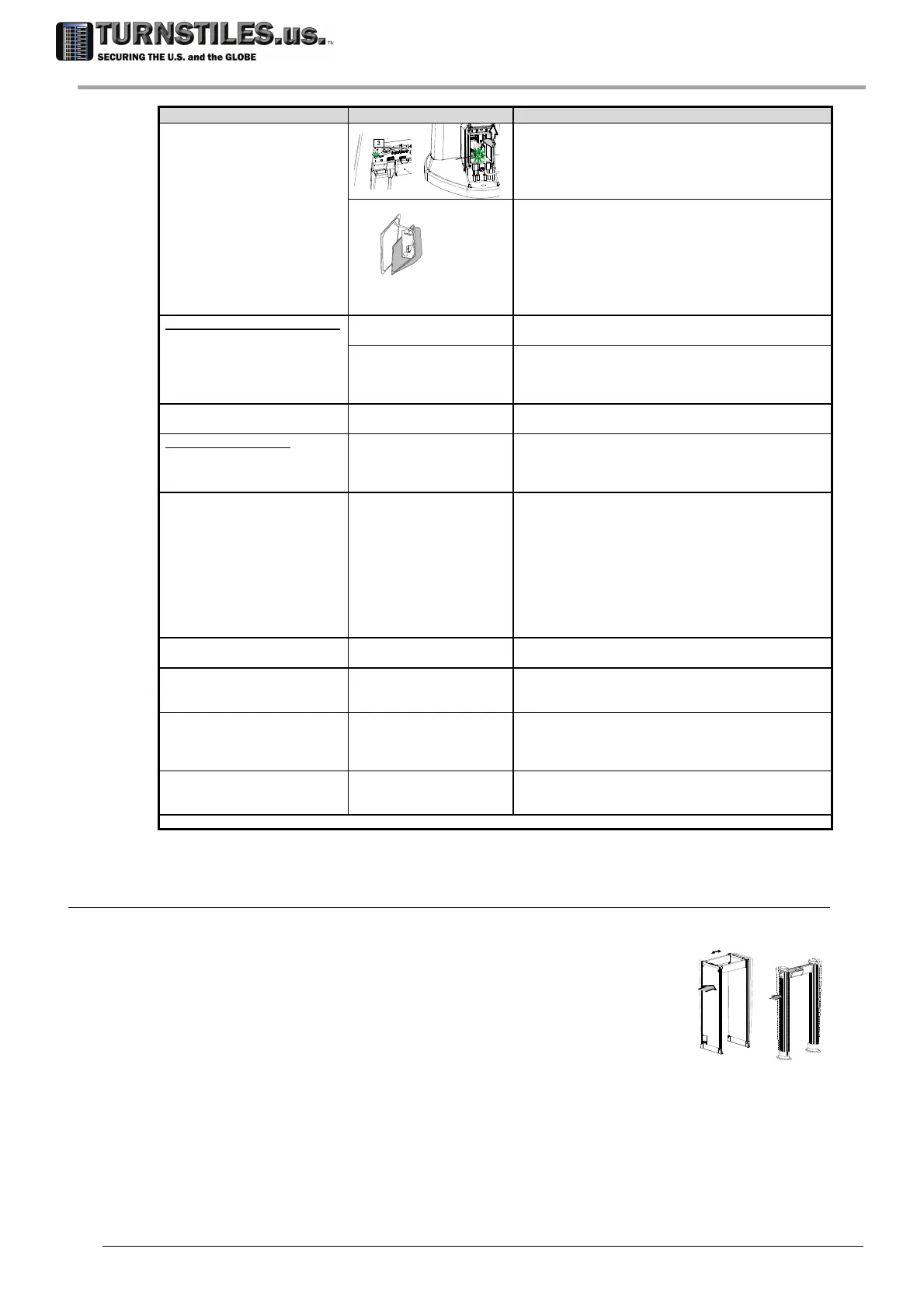
IOP card
Check all the power connections (mains cable,
control unit - TX antenna connecting cable) .
Check that the LED LINE on the lower connection
module is on.
If the LED LINE is off, replace the external PSA
power adapter.
If the LED LINE is on, replace the internal card of the
lower connection module .
Model with emergency batteries
Display off
Flat batteries. Connect the equipment to the mains supply and
recharge the batteries.
Malfunction of IOP card.
Check the battery voltages. Replace damaged
batteries.
Replace the internal card of the lower connection
module .
System in stand-by mode
(if supported).
Turn on the unit by using the MDO command (if
supported).
Model with photocells: no
passage detection.
malfunction of the
photocells.
Wrong programming of GD function: repeat OTS
procedure.
Dirty or defective photocell: check with the OTS
procedure. If necessary, replace it.
During OTS procedure:
ENA coverage <100%
EN readout > 3
Excessive environmental
electrical noise.
Run ENA step of OTS procedure after each one of the
following countermeasures:
Carry out a corrective action on any possible
interference source around the MD (see ‘Preliminary
Layout Inspection and Positioning’ section).
Change working channel CH, if applicable.
Swap the TX and RX antennas positions.
Rotate the archway, if it is possible.
Move the archway in a different position, if it is
possible.
No target detection at ground
level
Low sensitivity at ground
level
Start OTS procedure and carry out FGA step.
Increase LC parameter setting.
Excessive sensitivity at ground
level (f.i.: detection of shoes).
Excessive sensitivity at
ground level
Start OTS procedure and carry out FGA step.
Decrease LC parameter setting and verify target
detection.
False alarms generated by
mechanical vibrations.
Mechanical vibrations due,
for instance, to floor
oscillations, strong gusts of
air or wind.
Carry out EVA procedure.
False alarms generated by
repetitive movements of
innocuous large metal objects.
Large metal objects (f.i. a
metal trolley) moving near
the archway.
Decrease
SENT parameter until no false alarms occur (models
with photocell modules installed).
If the Metal Detector still does not operate properly, discontinue it and contact our Service Department for assistance.
NOTE: antenna and control unit can be replaced with corresponding spare parts, with no need of balance or loss of performance.
6.6.3 Procedure for compensating the environmental vibrations , EVA command
Scope of this procedure is to acquire and compensate the interferences generated by
mechanical vibrations caused by floor oscillations and strong gusts of air or wind.
Execute EVA programming command.
When the ‘PUSH’ message appears on the display, gently press the
side of the archway, making it oscillate (Remark: excessive force used
during EVA procedure will NOT result in a more successful adjustment).
As the device completes acquiring the applied vibration, the message
‘OK/EVA’ appears on the display.
ATTENTION! This acquisition procedure must be carried out for all Security Levels in use. Select any other IS setting in
use and repeat the acquisition procedure.
REMARK the application of the EVA compensation can be disabled through AVS command. This can be used in the
following cases:
In case the equipment is moved to a new location not subject to mechanical vibration.
To verify the effective improvement resulting from the EVA procedure (Floor)
303-670-1099