6
03
Installation
Operator’s Manual 2010 Rev B p/n 2010
OTE: N Specially ordered blowers with non-
standard construction, or with rotor end
clearances greater than shown in this
manual, will not have the operating limits
specied in Specications Table 3-1 on
page 6. Contact your Tuthill Vacuum &
Blower Systems sales representative for
specic information.
Specications Table
MODEL SERIES PORT SIZE
APPROXIMATE OIL
CAPACITY
MAXIMUM ALLOW-
ABLE DISCHARGE
TEMPERATURE
MAXIMUM
TEMPERATURE
RISE
MAXIMUM
PRESSURE
MAXIMUM
VACUUM
MAXIMUM
RPM
VERTICAL
FLOW
HORIZON-
TAL FLOW
3203
3208
AA
2 in. (51 mm)
3 in. (76 mm)
4 in. (102 mm)
4 in. (102 mm)
0.68 qt
(0.64 L)
0.38 qt
(0.36 L)
445°F (229°C) 325°F (163°C) 18 psig
17 inch-Hg
(576 mbar)
4,800
4606
4610
AA
4 in. (102 mm)
6 in. (152 mm)
6 in. (152 mm)
1.82 qt
(1.1 L)
1.07 qt
(1 L)
445°F (229°C) 325°F (163°C) 18 psig
17 inch-Hg/
(576 mbar)
4,000
6009
6015
AA
8 in. (203 mm)
8 in. (203 mm)
10 in. (254 mm)
4.68 qt
(4.4 L)
2.63 qt
(2.5 L)
445°F (229°C) 325°F (163°C) 18 psig
17 inch-Hg
(576 mbar)
3,200
Table 3-1 – Specifications
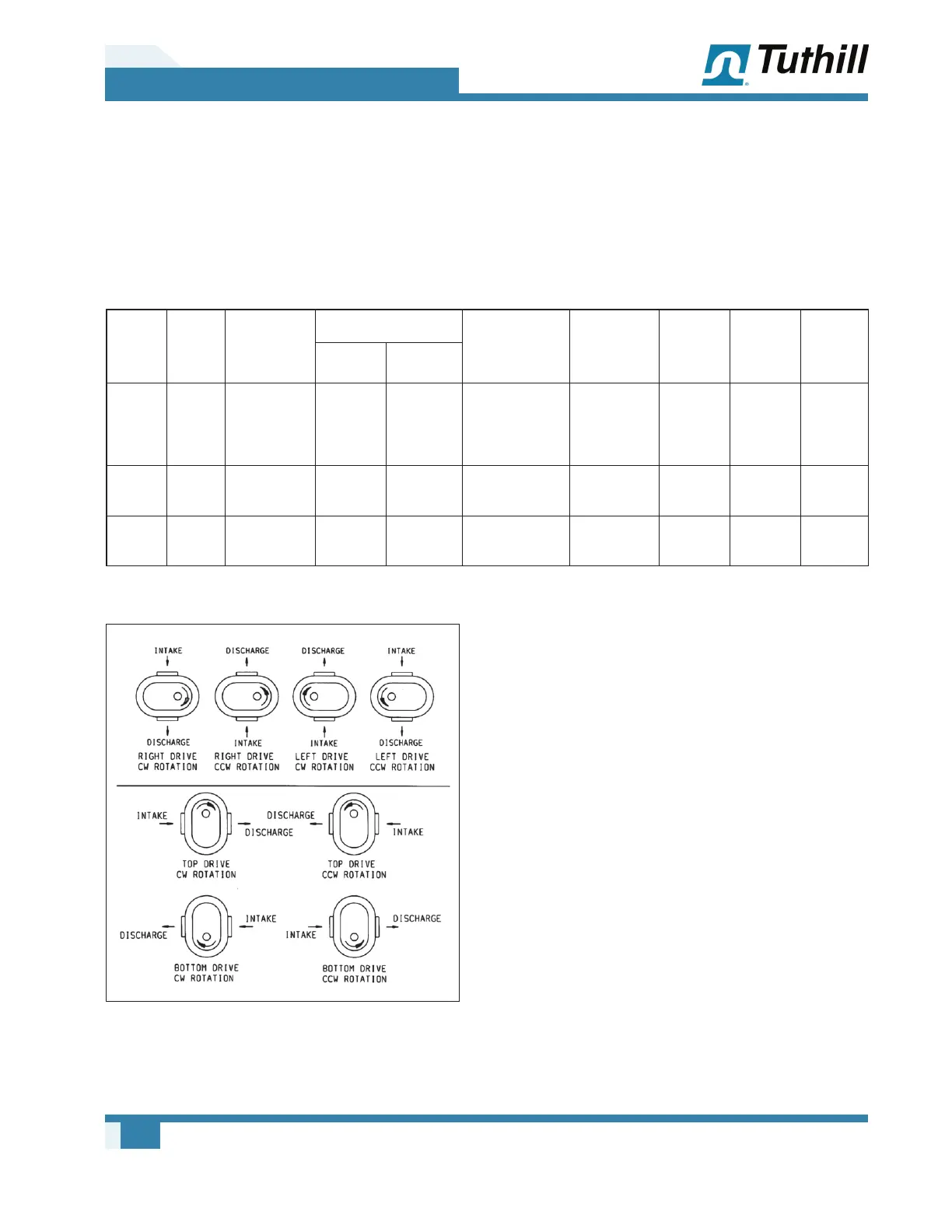
Figure 3-1 – Flow Direction by Rotation