9
03
Installation
Operator’s Manual 2010 Rev B p/n 2010
MOUNTING STRESS
Stress imparted from incorrectly aligned piping
or mounting will create problems with bearing
and seal life, possibly leading to premature
internal contact. The blower should sit stress-
free and evenly on its supporting surface. Take
care to evenly tighten the mounting bolts to avoid
imparting undue stress into the blower. Stress
can be checked in a free state with feeler stock or
veried on a previously installed blower with the
aid of a dial indicator. Spring or gap should be less
than 0.002 in. (0.05 mm).
BLOWER AIR INTAKE
To minimize maintenance, supply the blower with
the cleanest air possible. The air must not contain
any ammable or toxic gases, as the blower will
concentrate these gases. This could result in
damage to the blower and surrounding property
and lead to personal injury or death.
WARNING
!
Do not use air blowers on explosive or
hazardous gases. Each size blower has limits
on pressure differential, running speed, and
discharge temperature. These limits must not
be exceeded.
If it is necessary to take air from a remote source,
such as in a vacuum application, make sure the
diameter of the piping is at least the equal to the
diameter of the blower inlet. For distances greater
than 20 ft (6 m), enlarge the pipe diameter to
reduce inlet restriction. Excessive restriction will
reduce the efciency of the blower and elevate its
discharge temperature.
The piping used should also be corrosion-resistant
and free of scale and dirt. Keep the inlet covered to
keep out foreign objects and rain.
MOTOR DRIVES
Two drive connections commonly used are direct
drive and V-belt drive.
DIRECT COUPLED
When installing the motor directly to the blower,
align the shafts to the coupling according to the
coupling manufacturer’s instructions.
Blowers shipped with motor directly coupled and
mounted on a common base have been aligned
prior to shipment. Further alignment is not normally
necessary, but be sure to check the alignment and
make adjustments if necessary prior to starting the
blower.
V-BELTS
If the motor and blower are V-belt connected, the
sheaves on both the motor and blower shafts
should be as close to the shaft bearings as
possible. Blower sheave is not more than 1/4 in.
(6.5 mm) from the blower drive end cover. The
drive sheave is as close to the driver bearing as
possible. Take care when installing sheaves on
the blower and motor shafts. Make sure the face is
accurately in line to minimize belt wear.
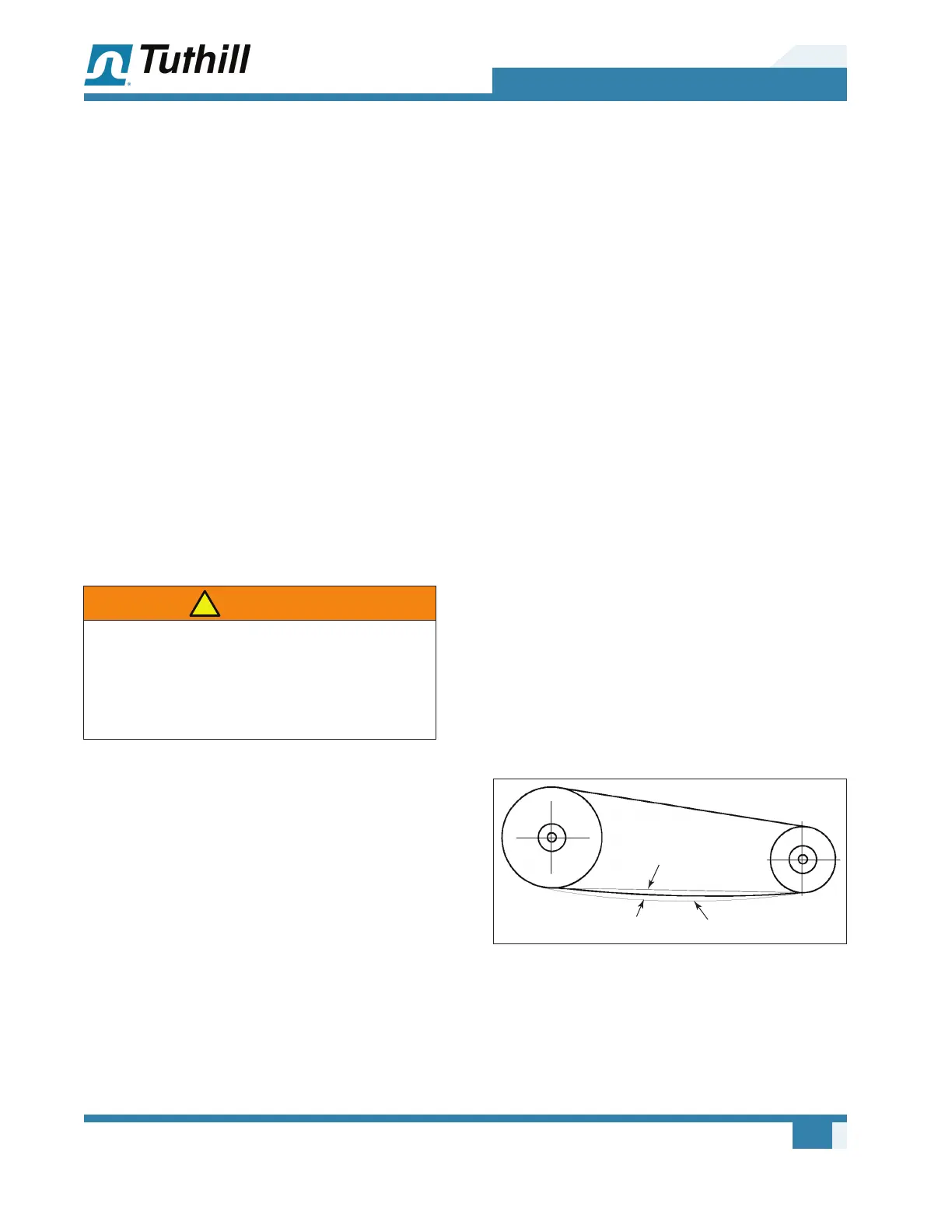
Adjust the belt tension to the manufacturer’s
specications using a belt tension tester. Check
new belts for proper tension after 24 hours of run
time. When manufacturer data is not available,
industry guidelines recommend 1/64 in. deection
for each inch of span (0.157 mm deection per
centimeter of span) at 8 to 10 lb (3.6 – 4.5 kg) of
force in the center of the belt. See Figure 3-3.
Too Tight
Slight Bow
Too Loose
20/64” = 5/16” (8 mm)
20”
(50.8 cm)
8-10 lbs.
(3.6-4.5 kg)
Figure 3-3 – General appearance of V-belt drive