Operator’s Manual 1808 022016 ENG
10
05
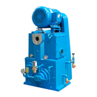
Installation
DIRECT DRIVE
ounted the pump on a fl at and level surface. f
the pump is to be installed outdoors, ensure the
motor, painting, peripheral equipment, parts, etc.,
are suitable for outdoor operation. Allow enough
space around the pump for safe maintenance
work and periodic inspections. This includes, at
a minimum, the ability to access oil fi ll and drain
locations and to vi ew the oil leve l sight glass.
The K D series Drive -Drive models are direct drive n
by two methods
• 8 pole (K D5 0) or 12 pole (K D30) motors
• ear reducer driven by or pole motor
f the pump was purchased directly from Tuthill,
the coupling has been factory-aligned and tested.
When installing the pump alone to be direct-
coupled to a motor or gear drive , ensure the
coupling alignment meets the manufacturer’s
recommendations to avoid ecessive loading of the
pump or motor bearings.
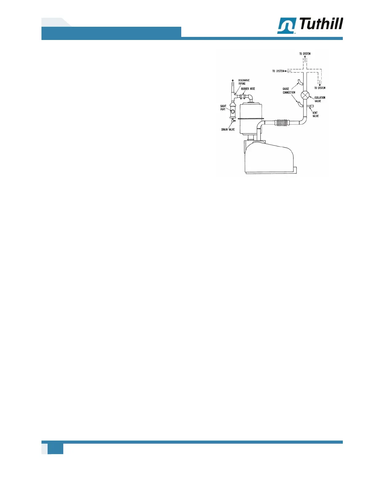
DISCHARGE PIPING
t may be desirable to connect discharge piping
from the oil separator to the outside to dispose
of ehaust gases and vapors. See Figure 5 -2 on
page 10 . When connecting discharge piping,
place a dropout trap adacent to the oil separator
to trap the condensate, which would otherwise
drain back into the oil. If the condensate is water,
drain it as necessary to prevent it from fl owing
back into the reservoir. A fl eible connector, such
as a rubber hose, at the discharge of the pump
is necessary to make the piping fl eible and to
provi de a conve nient disconnect point for servi cing.
Turned down the outside end of the discharge line
to prevent entry of precipitation.
Figure 5-2 – Typical Manifold Arrangement
INLET PIPING
Size and design the inlet piping with three
obectives in mind
• To prevent undue gas fl ow restriction
• To prevent pump fl uids from splashing into the
process chamber
• To protect the pump from inection of particulate
matter
Tuthill recommends that the va cuum piping to the
pump inlet be as large in diameter and as short
in length as possible and no smaller in diameter
than the pump inlet. See Figure 5 -2 on page
10 for recommended arrangement of va cuum
manifolding.
As with all rotary mechanical pumps, it is
necessary to install a fl eible member in
the suction manifold of the pump to avo id
alignment problems and to reduce the possibility
of transmitting vi bration to and from other
components. elf-supporting, bellows-type, fl eible
connectors are recommended and are av ailable
from Tuthill V acuum & B lower. Use a connector be
fl eible enough to prevent vibration transmission
and yet rigid enough to prevent collapsing under
high va cuum.
 Loading...