TFP610
Page 4 of 28
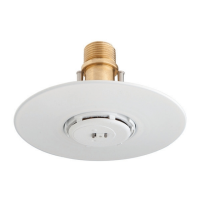
AP Sprinkler (Attic Plus)
The AP Sprinklers are to be installed
in the upright orientation with their de-
flector parallel to the roof. The Model
AP Sprinklers (Figure F) are intended
to be used to provide protection of at-
tic areas outside the scope of appli-
cations for the BB, SD, or HIP Sprin-
klers. The AP Sprinklers must only
be used in conjunction with other
Specific Application Attic Sprinklers,
i.e., BB, SD, and HIP, or as permitted
in other sections of this document.
When used, the AP Sprinklers will pro-
vide a hydraulic advantage over Stan-
dard Spray Sprinklers for the protec-
tion of attic areas outside the scope
of application for the BB, SD, or HIP
Sprinklers.
NOTICE
The Specific Application Sprinklers
for Protecting Attics described here-
in must be installed and maintained
in compliance with this document, as
well as with the applicable standards
of the National Fire Protection Asso-
ciation, in addition to the standards of
any other authorities having jurisdic-
tion. Failure to do so may impair the
performance of these devices.
The owner is responsible for main-
taining their fire protection system
and devices in proper operating con-
dition. Contact the installing contrac-
tor or product manufacturer with any
questions.
Sprinkler
Identification
Number (SIN)
TY4180* - BB1, K=8.0
TY4181* - BB2, K=8.0
TY4182* - BB3, K=8.0
TY3180* - BB1, K=5.6
TY3181* - BB2, K=5.6
TY3182* - BB3, K=5.6
TY2180 - BB1, K=4.2
TY2181 - BB2, K=4.2
TY2182 - BB3, K=4.2
TY3183* - SD1, K=5.6
TY3184* - SD2, K=5.6
TY3185* - SD3, K=5.6
TY3187* - HIP, K=5.6
TY3190 - AP, K=5.6
TY2190 - AP, K=4.2
* The “TY” prefix is a re-designation of
the previous “C” prefix (e.g., TY4180 is
a re-designation for C4180).
Technical
Data
Approvals
UL & C-UL Listed
(These Approvals only apply to the
service conditions indicated in the De-
sign Criteria section on Page 6 and the
Design Guidelines section on Page 8.)
Pipe Thread Connection
1/2 inch NPT for K=4.2 & 5.6
3/4 inch NPT for K=8.0
Discharge Coefficient
K = 4.2 gpm/psi
1/2
(60,5 lpm/bar
1/2
)
K = 5.6 gpm/psi
1/2
(80,6 lpm/bar
1/2
)
K = 8.0 gpm/psi
1/2
(115,5 lpm / bar
1/2
)
Temperature Rating
Intermediate Temperature as follows:
-200°F (93°C) for BB (K4.2 & K8.0),
H IP, A P
-212°F (100°C) for BB (K5.6), SD
Finish
Natural Brass
Physical Characteristics
(Figures A, C & E)
Frame ............................Bronze
Button..................... Bronze/Copper
Sealing Assembly ...........Beryllium Nickel
w/TEFLON
Bulb .....................Glass (3 mm dia.)
Link...............................Monel
Compression Screw . . . . . . . . . . . . . . . . . Brass
Deector.....................Brass/Bronze
Physical Characteristics
(Figures B & D)
Body.............................. Brass
Cap..............................Bronze
Sealing Assembly ...........Beryllium Nickel
w/TEFLON
Saddle ............................Brass
Link Assembly . . . . . . . . . . . . . . . . . . . . . . Nickel
Compression Screw . . . . . . . . . . . . . . . . . Brass
Deector.....................Brass/Bronze
Lever.....................Bronze Deector
Frame ............................Bronze
Diffuser............................Brass
Rivet .............................. Brass
Physical Characteristics
(Figure F)
Frame .............................Brass
Button............................Bronze
Sealing Assembly ...........Beryllium Nickel
w/TEFLON
Bulb .....................Glass (3 mm dia.)
Compression Screw . . . . . . . . . . . . . . . . . Brass
Deector..........................Bronze
Operation
BB (K=8.0 & 4.2), HIP (K=5.6) &
AP (5.6 & 4.2)
The glass bulb contains a fluid that ex-
pands when exposed to heat. When
the rated temperature is reached, the
fluid expands sufficiently to shatter
the glass bulb, allowing the sprinkler
to activate and water to flow.
BB (K=5.6) & SD (K=5.6)
The fusible link assembly is comprised
of two link halves which are joined by
a thin layer of solder. When the rated
temperature is reached, the solder
melts and the two link halves sepa-
rate, allowing the sprinkler to activate
and water to flow.
 Loading...