TFP633
Page 2 of 8
Design Criteria,
CPVC Pipe
Area of Use (CPVC Pipe)
Horizontal (slope not exceeding 2:12)
combustible concealed spaces of:
• Unobstructed wood truss construc-
tion or unobstructed bar joist con-
struction (Ref. Figure 2).
• Non-combustible, insulation-filled
solid wood or composite wood joist
construction (Ref. Figure 3).
NOTE: In order to be considered
“non-combustible insulation-filled
solid wood or composite wood joist
construction,” the insulation (includ-
ing insulation provided with a combus-
tible vapor barrier), must completely fill
the pockets between the joists to the
bottom of the joists, and the insulation
must be secured in place with metal
wire netting. The metal wire netting is
intended to hold the insulation in place
should the insulation become wetted
by the operation of the Model CC3
Sprinklers in the event of a fire.
Concealed Space Area (CPVC Pipe)
The area of the concealed space is not
limited; however, for both Figure 2 and
Figure 3, where CPVC pipe is being uti-
lized, draft curtains or full height walls
must be provided at 1000 ft² (93 m²)
areas. This draft curtain shall be at
least 1/3 the depth of the concealed
space or 8 in. (200 mm), whichever
is greater, and be constructed using
a material that will not allow heat to
escape through or above the draft
curtain.
Concealed Space Size (CPVC Pipe)
The depth of the concealed space is
60 in. (1524 mm) maximum to 6 in. (152
mm) minimum.
System Type (CPVC Pipe)
Light hazard, wet pipe system
Maximum Distance Between Model
CC3 Sprinklers (CPVC Pipe)
TY2199 4.2K. . . . . . . . . . . . . . 14 ft (4,3 m)
TY3199 5.6K. . . . . . . . . . . . . . 16 ft (4,9 m)
Maximum Coverage Area
(CPVC Pipe)
TY2199 4.2K. . . . . . . . . . . 196 ft² (18,2 m²)
TY3199 5.6K. . . . . . . . . . . 256 ft² (23,8 m²)
Minimum Distance Between Model
CC3 Sprinklers (CPVC Pipe)
Minimum sprinkler spacing is 7 ft
( 2,1 m)
NOTE: Minimum spacing does not
apply to any additional sprinklers
required for protection of CPVC pipe
that is offset over an obstruction.
Deflector Position (CPVC Pipe)
• 1-1/2 in. to 4 in. (40 to 100 mm) below
upper deck for wood truss construc-
tion or bar joist construction (Ref.
Figure 2)
• 1-1/2 in. to 4 in. (40 to 100 mm) below
solid wood or composite wood joists
(Ref. Figure 3)
Minimum Distance Away From
Trusses (CPVC Pipe)
4-1/2 in. (114 mm)
Remote Area (CPVC Pipe)
The remote area is 1000 ft² (93 m²)
NOTE: The remote area does not
include any additional sprinklers
required for protection of CPVC pipe
that is offset over an obstruction.
Required Minimum Density
(CPVC Pipe)
0.10 gpm/ft² (4,1 mm/min)
Minimum Operating Pressure
(CPVC Pipe)
7 psi (0,48 bar)
Obstructions (CPVC Pipe)
See Figure 8 in this data sheet for
obstructions rules.
Use of UL Listed BLAZEMASTER
CPVC Pipe with Model CC3
Sprinklers
BLAZEMASTER CPVC product may
be used in concealed spaces requir-
ing automatic sprinklers, when used in
conjunction with Model CC3 Sprinklers.
In order to use the BLAZEMASTER
CPVC product for wood truss or bar
joist construction, the horizontal run of
pipe must be a maximum of 6 in. (150
mm) above the ceiling or noncombus-
tible ceiling insulation, or 1/3 the depth
of concealed space (as measured
from the top surface of the ceiling to
the bottom of the deck above), which-
ever is smaller (Ref. Figure 2). For insu-
lation-filled solid wood or composite
wood joist construction, the horizon-
tal run of pipe must be a maximum of
6 in. (150 mm) above ceiling or non-
combustible ceiling insulation, or 1/3
the depth of concealed space (as
measured from the top surface of the
ceiling to the bottom surface of the
joist insulation above), whichever is
smaller (Ref. Figure 3). The CPVC pipe
can then be used to supply the Model
CC3 Sprinklers, as well as the sprin-
klers below the ceiling. Unless modified
by this technical data sheet, all other
guidelines of the “BLAZEMASTER —
Installation Instructions & Technical
Manual” must be met. When using 1
in. (DN25) or larger pipe, a hanger must
be located at the truss nearest a sprig
for purposes of restraint. If using 3/4 in.
(DN19) piping, all sprigs over 12 inches
(305 mm) must be laterally braced
using methods described in the NFPA
standards.
Where the CPVC must be offset up
and over an obstruction and the pipe
exceeds the allowed horizontal posi-
tioning requirements specified above
as well as shown in Figure 2 and 3,
additional Model CC3 Sprinklers are
to be installed as shown in Figures 2
and 3 to protect the BLAZEMASTER
CPVC product.
A minimum lateral distance of 18 in.
(460 mm) must be maintained between
the CPVC pipe and heat pumps, fan
motors, and heat lamps.
-
-
-
-
-
-
-
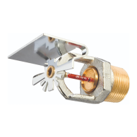
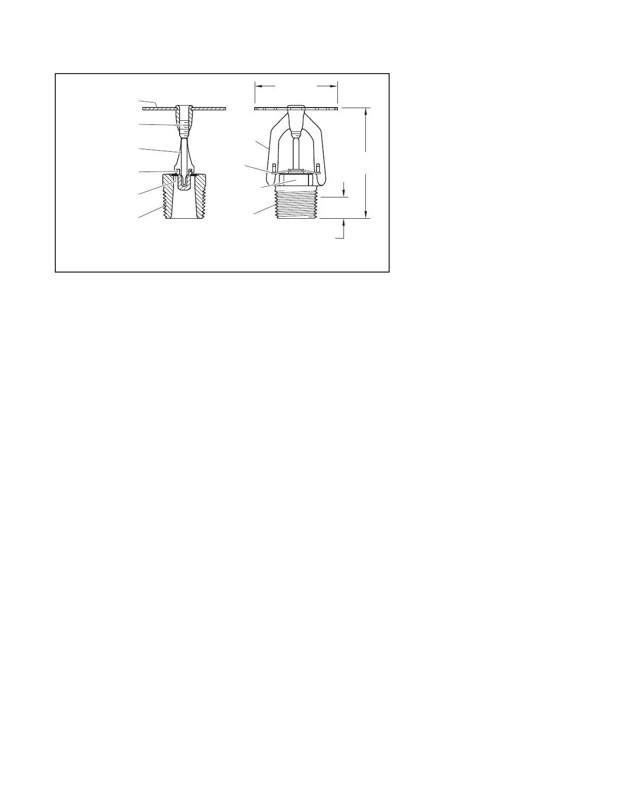
Frame
Button
Sealing
Assembly
Deector
Bulb
Compression
Screw
2
1
3
4
Components:
5
6
WRENCH
FLATS
7/16" (11,1 mm)
SPRINKLER
FRAME
ARMS
(42,9 mm)
2-1/4"
1/2" NPT
7
Ejection
Spring
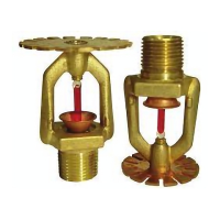
FIGURE 1
MODEL CC3 SPRINKLER

 Loading...