TFP633
Page 7 of 8
Installation
The Model CC3 Sprinklers must be
installed in accordance with this
section.
General Instructions
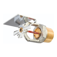
The Model CC3 Sprinklers are to be
installed upright and with their frame
arms (Ref. Figure 1) in-line with the
pipe run (Ref. Figures 2 through 7, as
applicable).
Do not install any bulb type sprinkler
if the bulb is cracked or there is a loss
of liquid from the bulb. With the sprin-
kler held horizontally, a small air bubble
should be present. The diameter of the
air bubble is approximately 1/16 in.
(1,6 mm) for the 200°F (93°C) tempera-
ture rating.
A leak-tight 1/2 in. NPT sprinkler joint
should be obtained with a torque of 7 to
14 lb-ft (9,5 to 19,0 N∙m). Higher levels
of torque may distort the sprinkler inlet
with consequent leakage or impairment
of the sprinkler.
The Model CC3 Sprinklers must only
be installed in the upright position with
the deflector parallel to the upper deck.
With pipe thread sealant applied to the
pipe threads, use only the W-Type 6
(End A) Sprinkler Wrench (Ref. Figure
9) for installation of the Model CC3
Sprinklers by applying the wrench to
the sprinkler wrench flats only.
(USE END "A"
ONLY)
0"
2-1/2"
(63,5 mm)
3-1/2"
(88,9 mm)
5-1/2"
(139,7 mm)
7-1/2"
(190,5 mm)
9-1/2"
(241,3 mm)
12"
(304,8 mm)
14"
(355,6 mm)
16-1/2"
(419,1 mm)
(0 mm)
Distance of Deector
Above Bottom of
Obstruction
(B)
Centerline of
Sprinkler to Side
of Obstruction
(A)
A≥3C or 3D
A≤24" (609,6 mm)
(Use dimension C or D, whichever is greater)
<12"
<(304,8 mm)
12" to <18"
(304,8 mm to <457,2 mm)
18" to <24"
(457,2 mm to <609,6 mm)
24" to <30"
(609,6 mm to <762,0 mm)
30" to <36"
(762,0 mm to <914,4 mm)
36" to <42"
(914,4 mm to <1066,8 mm)
42" to <48"
(1066,8 mm to <1219,2 mm)
48" to <54"
(1219,2 mm to <1371,6 mm)
54" to <60"
(1371,6 mm to <1524,0 mm)
NOTE:
WEB MEMBERS AND GUSSETS
SHALL NOT BE CONSIDERED
OBSTRUCTIONS PROVIDED THE
MINIMUM 4-1/2 INCH LATERAL
DISTANCE (FIG. 2) REQUIRED
BY THE SPECIFIC APPLICATION
LISTING IS MAINTAINED.
OBSTRUCTION
MODEL CC3
SPRINKLER
C
D
A
OBSTRUCTION
UPPER
DECK
LOWER
DECK
A
MODEL CC3
SPRINKLER
MODEL CC3
SPRINKLER
A
UPPER DECK
OR BOTTOM OF
NON-COMUSTIBLE
INSULATION
B
C
D
OBSTRUCTION
FIGURE 9
W-TYPE 6 SPRINKLER
WRENCH
FIGURE 8
NFPA 13 OBSTRUCTION TO WATER DISTRIBUTION CRITERIA
(REFERENCE)

 Loading...