TFP633
Page 4 of 8
Design Criteria,
Steel Pipe
Area of Use (Steel Pipe)
Horizontal (slope not exceeding 2:12)
combustible concealed spaces of:
• unobstructed wood truss construc-
tion or unobstructed bar joist con-
struction, see Figure 5
• solid wood joist construction, see
Figure 6, where the upper deck and
ceiling joists may have a maximum
depth of 12 inches (300 mm) and typ-
ical on center joist spacing of mini-
mum 16 inches (400 mm).
• non-combustible insulation-filled
solid wood joist or wood composite
joist construction, see Figure 7
• Obstructed wood truss construction,
see Figure 8
NOTE: In order to be considered “non-
combustible insulation-filled solid
wood joist or composite wood joist
construction”, the insulation (includ-
ing insulation provided with a combus-
tible vapor barrier), must completely fill
the pockets between the joists to the
bottom of the joists, and the insulation
must be secured in place with metal
wire netting. The metal wire netting is
intended to hold the insulation in place
should the insulation become wetted
by the operation of the Model CC3
Sprinklers in the event of a fire.
Concealed Space Area (Steel Pipe)
The area of the concealed space is not
limited; however,
• For unobstructed wood truss con-
struction or concealed spaces of
non-combustible, unobstructed
bar joist construction, see Figure
5, draft curtains or full height walls
must be provided at 1000 ft² (93 m²)
areas. In addition, the 5.6K sprinkler
is UL Listed for a 2000 ft² (186 m²)
draft curtain area as well as without
draft curtains for unobstructed solid
wood truss construction on edge
or on face or unobstructed bar joist
construction.
This draft curtain shall be at least 1/3
the depth of the concealed space or
8 in. (200 mm), whichever is greater,
and be constructed using a mate-
rial that will not allow heat to escape
through or above the draft curtain.
• For solid wood joist construction, see
Figure 6, and obstructed wood truss
construction, see Figure 8:
Blocking must be provided in each
upper deck and ceiling joist channel
at a maximum 32 ft (9,75 m) inter-
vals. This blocking shall be installed
to the full depth of the joists and be
installed so as to not allow heat to
escape through or above the block-
ing. The blocking must be con-
structed using a non-combustible
material or the joist construction
material.
Draft curtains must protrude below
the joist a minimum of 6 inches (150
mm) or 1/3 the depth of the con-
cealed space, whichever is greater,
and run parallel with the joist spaced
at 31 ft (9,4 m) width maximum to
limit the area to a maximum of 1000
ft² (93 m²). For information about the
use of antifreeze see the Technical
Data section.
The draft curtains are to be con-
structed using a material that will
not allow heat to escape through or
above the draft curtain.
• For non-combustible, insulation-lled
solid wood joist or composite wood
joist construction, see Figure 7, the
requirement for draft curtains and
blocking does not apply.
• For information about the use of
antifreeze see the Technical Data
section.
Concealed Space Size (Steel Pipe)
The minimum and maximum concealed
space depth is as follows:
For unobstructed wood truss construc-
tion or concealed spaces of unob-
structed bar joist construction, see
Figure 5, the maximum depth of the
concealed space is 60 in. (1524 mm)
from bottom of upper deck to top of
ceiling, and the minimum depth is 6 in.
(152 mm) from the bottom of the upper
chords to the top of the lower chords.
For solid wood joist construction, see
Figure 6, and solid wood or composite
wood joist construction the maximum
depth of the concealed space is 84 in.
(2134 mm) from bottom of upper deck
to top of ceiling, and the minimum
depth is 6 in. (152 mm) from the bottom
of the upper deck joists to the top of
the ceiling joists. If joist construction is
lled with non-combustible insulation
the maximum height of the space is 84
in. (2134 mm). See Figure 6.
For obstructed wood truss construc-
tion, see Figure 8, the maximum
depth of the concealed space is
84 in. (2134 mm) from bottom of upper
deck to top of ceiling, and the minimum
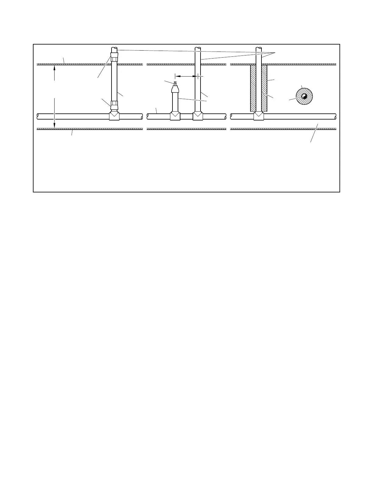
OPTION 1 OPTION 2 OPTION 3
MODEL CC3
SPRINKLER
ABOVE
CPVC
TO STEEL
TRANSITION
FITTING
CPVC
PIPE
6" (152 mm) MAXIMUM CLEARANCE FOR CPVC PIPE TO CEILING OR NON-COMBUSTIBLE CEILING
INSULATION, OR 1/3 DEPTH OF ACTUAL CONCEALED SPACE (MEASURED FROM TOP SURFACE
OF CEILING TO BOTTOM SURFACE OF FLOOR DECK ABOVE), WHICHEVER IS SMALLER
(4" (100 mm) FOR 12" (300 mm) TRUSS)
NON-COMBUSTIBLE
CEILING
CONCEALED
SPACE
24" (600 mm)
MAXIMUM
CPVC
PIPE
THROUGH FLOOR
STEEL
PIPE
CPVC
PIPE
1/2" (12,5 mm) WRAP
NON-COMBUSTIBLE
INSULATION
FIGURE 4
VERTICAL RISERS IN COMBUSTIBLE CONCEALED SPACE THROUGH FLOOR ABOVE
INSTALLATION OPTIONS CROSS SECTION ELEVATION VIEW
CPVC PIPE
 Loading...