TFP633
Page 5 of 8
depth is 6 in. (152 mm) from the bottom
of the upper chord to the top of the
lower chord.
System Type (Steel Pipe)
Light hazard, wet or dry pipe system
NOTES: Use of the 4.2K sprinklers in
dry pipe systems is permitted by section
8.3.4.4 of NFPA 13 (2013 edition) where
piping is corrosion resistant or internally
galvanized.
Maximum Distance Between
Model CC3 Sprinklers (Steel Pipe)
TY2199 4.2K. . . . . . . . . . . . . . .14 ft (4,3 m)
TY3199 5.6K. . . . . . . . . . . . . . 16 ft (4,9 m)
Maximum Coverage Area
(Steel Pipe)
TY2199 4.2K. . . . . . . . . . . 196 ft² (18,2 m²)
TY3199 5.6K. . . . . . . . . . . 256 ft² (23,8 m²)
Minimum Distance Between
Model CC3 Sprinklers (Steel Pipe)
Minimum sprinkler spacing is 7 ft
(2,1 m)
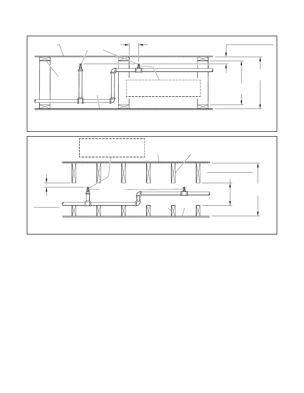
Deflector Position (Steel Pipe)
1-1/2 in. to 4 in. (40 mm to 100 mm)
below upper deck for wood truss con-
struction or concealed spaces of non-
combustible bar joist construction, see
Figure 5.
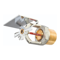
1-1/2 in. to 2 in. (40 to 50 mm) below
solid wood joist, see Figure 5, or top
chord of a wood truss that has a depth
greater than 4 in, see Figure 8.
1-1/2 in. to 4 in. (40 to 100 mm) below
non-combustible insulation-lled solid
wood joists or composite wood joists,
see Figure 7.
Remote Area (Steel Pipe)
The remote area for wood truss con-
struction or bar joist construction, see
Figure 5, solid wood joist construc-
tion, see Figure 6, or obstructed wood
truss construction, see Figure 8, is
1000 ft² (93 m²) for wet pipe or dry pipe
systems.
The remote area for unobstructed
solid wood truss construction or unob-
structed bar joist construction without
the use of draft curtains is 9 sprinklers
or 1000 ft² (93 m²), whichever is greater,
for both wet pipe or dry pipe systems.
The remote area for non-combusti-
ble insulation-lled solid wood joist
or wood composite joist construction,
see Figure 7, without draft curtains is
to be calculated per the requirements
of NFPA 13.
Required Minimum Density
(Steel Pipe)
0.10 gpm/ft² (4,1 mm/min)
Minimum Operating Pressure
(Steel Pipe)
7 psi (0,48 bar)
Obstructions (Steel Pipe)
See Figure 9 in this data sheet for
obstructions rules.
MODEL CC3
SPRINKLER
60" (1524 mm)
MAXIMUM
FRAME ARMS OF SPRINKLER
MUST BE INSTALLED IN-LINE
WITH PIPE RUN
FROM FACE OF WOOD TRUSS
OR TOP CHORD OF BAR JOIST
TOP CHORD
4" (102 mm)
OR LESS
6" (152 mm)
MINIMUM
CEILING
4" (102 mm) MAXIMUM
FRAME ARMS OF SPRINKLER
MUST BE INSTALLED
IN-LINE WITH PIPE RUN
UPPER
DECK
CEILING
FRAMING
MAXIMUM
2x FLOOR SOLID
WOOD JOISTS
MODEL CC3
SPRINKLER
MINIMUM
2" (51 mm)
MAXIMUM
60" (1524 mm) MAXIMUM
6" (152 mm) MINIMUM
CEILING
FIGURE 5
UNOBSTRUCTED WOOD TRUSS CONSTRUCTION OR UNOBSTRUCTED BAR JOIST CONSTRUCTION
CROSS SECTION ELEVATION VIEW
STEEL PIPE
FIGURE 6
SOLID WOOD JOIST CONSTRUCTION CROSS SECTION ELEVATION VIEW
STEEL PIPE