TFP720
Page 7 of 8
DO route the FASTFLEX Flexible Hose to permit complete
draining either back into the branch-line or through the
sprinkler reducer.
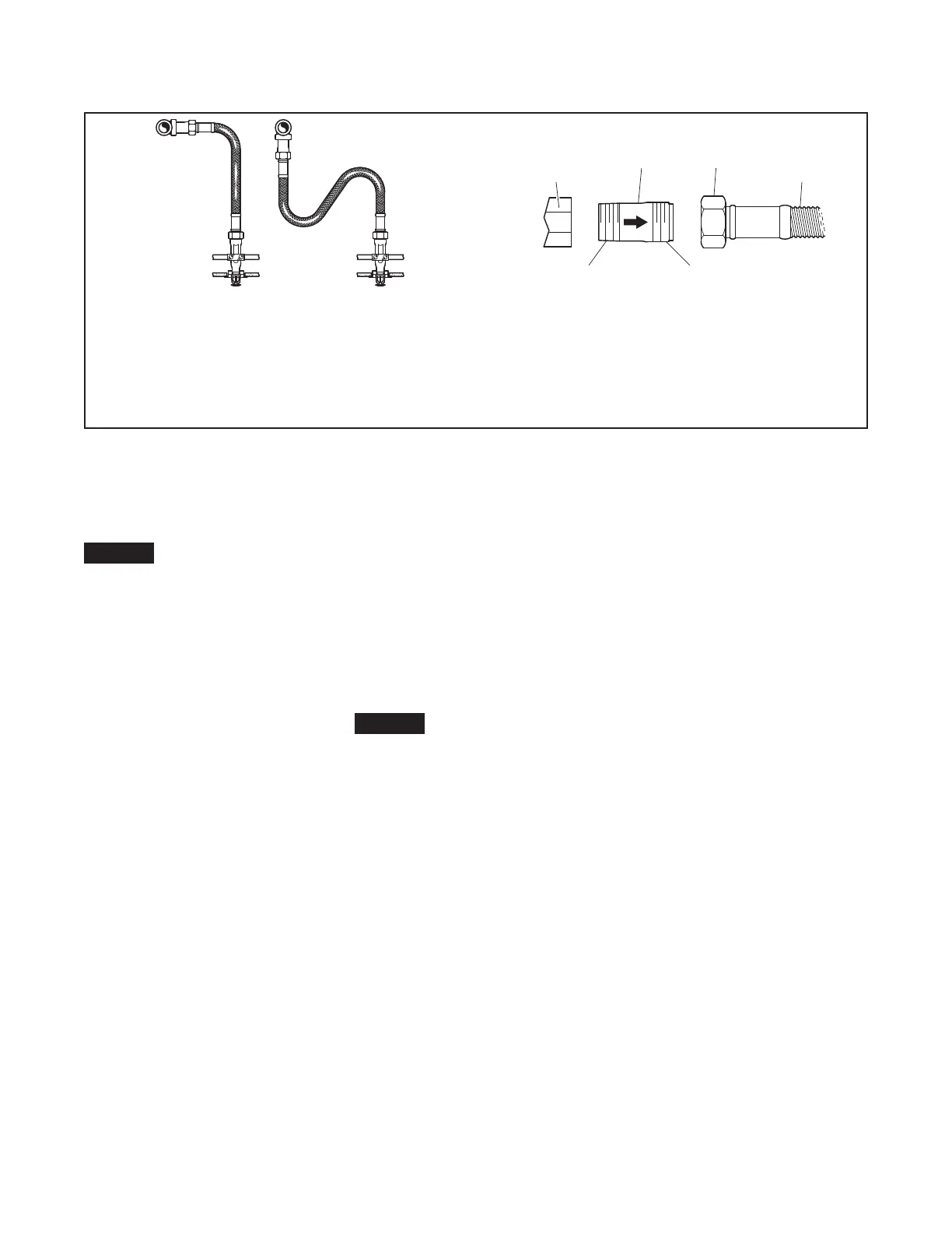
DO assemble the FASTFLEX Inlet Nipple with the direc-
tion of flow arrow properly oriented to avoid mismatched
threads.
Installation
The TYCO FASTFLEX Flexible Sprin-
kler Hose as shown in Figure 1, must
be installed in accordance with this
section.
NOTICE
Flexible Hoses are intended only to
connect sprinklers directly to system
piping (Ref. Figure 1). Flexible Hoses
cannot be joined together to form
longer hoses. Joining Flexible Hoses
together creates an assembly with
unknown performance that has not
been accounted for in system calcula-
tions or safe product performance.
Step 1. Review the Design Criteria
section that applies to the Approval
agency recognized by the authority
having jurisdiction, as well as Figure 3
that provides installation guidance.
Step 2. Determine the approximate
place where the sprinkler will be
located. The Support Bar is 700 mm
long and shall be mounted on the
600 mm width of the ceiling grid. The
sprinkler should be located as close as
possible to the center of the distance
between ceiling grid T-bars.
Step 3. Slide the Reducer Bracket
onto the Support Bar. Loosely attach
the Reducer Bracket and the two Bar
Fixing Clamps on the Support Bar and
place the Bar Fixing Clamps such that
the Support Bar crosses the location
where the sprinkler will be located.
Step 4. Attach one end of the Flex-
ible Hose onto the sprinkler reducer.
Applying the wrench to the Slip Nut,
and not to the Flexible Hose, tighten to
a maximum torque of 35 Nm.
Step 5. Attach the Inlet Nipple on to the
branch line. Ensure that the arrow is in
the appropriate direction of flow to the
sprinkler and to use pipe thread sealant
at the connection to the branch line.
Attach one end of the Flexible Hose on
to the Inlet Nipple. Applying the wrench
to the Slip Nut, and not to the Flexible
Hose, tighten to a maximum torque of
35 Nm. Do not twist the Flexible Hose.
Step 6. Bend the Flexible Hose into
a curve(s) that locates the Sprinkler
Reducer at the other end of the Flexible
Hose in the area where the sprinkler will
be located. The tube arc should not be
twisted, and the arc should be as large
and smooth as possible.
NOTICE
For minimum bend criteria, refer to the
Design Criteria section that applies to
the Approval agency recognized by the
authority having jurisdiction.
A bend radius smaller than pro-
vided by the minimum bend criteria
may adversely effect the friction loss
specifications stated by the approval
laboratory.
For assembly lengths greater than
1800 mm the Flexible Hose shall be
supported to the structure to ensure
that the maximum unsupported length
does not exceed 1800 mm. In these
cases, it is recommended that the tube
be secured to a fixed mounting point
every 600 mm, in order to provide a
more stable installation.
Step 7. Insert the Sprinkler Reducer
into the Reducer Bracket. Locate
the Reducer Bracket and Sprinkler
Reducer where the sprinkler will be,
and loosely tighten the Butterfly Bolt
on the Reducer Bracket.
Step 8. Attach the sprinkler to the
Sprinkler Reducer. Put a wrench on
the Sprinkler Reducer to counteract the
tightening torque and prevent the Flex-
ible Hose from twisting. Reference the
sprinkler manufacturer’s sprinkler data
sheet for appropriate sprinkler tighten-
ing torque, sprinkler wrench, and other
guidance.
Step 9. Verify that the Sprinkler
Reducer is seated in the Reducer
Bracket. Precisely locate the sprin-
kler in all three axes in accordance
with the sprinkler manufacturer’s data
sheet. Tighten the Butterfly Bolts on
the Bar Fixing Clamps and the Reducer
Bracket. The tightening torque for the
Bar Fixing Clamp fastener is 4,5 to
5,7 Nm, and the tightening torque for
the Reducer Bracket fastener, is a
minimum of 2,3 Nm.
Step 10. After tightening all the But-
terfly Bolts, verify that the sprinkler is
properly located in accordance with
the manufacture’s instructions. If not,
loosen the Butterfly Bolts and readjust
as required.
ISO 7-R 1
OR ISO 7-R 1 1/4
MACHINE HOSE
THREADED
FITTING
OUTLET
NUT
HOSE TO
NIPPLE
FIGURE 3
FASTFLEX FLEXIBLE SPRINKLER HOSE
INSTALLATION GUIDANCE
 Loading...