TFP645
Page 6 of 8
Step A. With reference to dimensions
provided in Figure 8, install sprinkler
fitting at proper distance above finished
suspended ceiling level and cut clear-
ance hole centered on sprinkler fitting
through ceiling panel.
Note: Ensure ceiling panel is properly
installed before proceeding to sprinkler
installation in remaining steps.
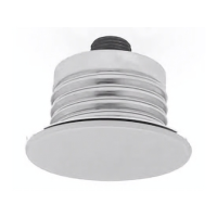
Step B. Assemble Dust Cap onto
Sprinkler. Ensure Dust Cap is flush
against sprinkler body mating surface.
Step C. Apply sealant to external
threads of sprinkler inlet. With hex end
of thread extension oriented toward
sprinkler inlet, hand-tighten onto sprin-
kler threads.
NOTICE
Ensure sealant avoids contact with
sprinkler guide pins and internal water-
way of sprinkler inlet. Failure to do so
may result in equipment failure.
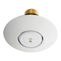
Step D. Assemble Escutcheon onto
sprinkler body. Ensure Escutcheon is
flush against sprinkler body mating
surface. Apply sealant to external
threads of thread extension.
NOTICE
Ensure sealant avoids contact with
sprinkler guide pins and internal water-
way of thread extension. Failure to do
so may result in equipment failure.
Step E. Engage Sprinkler by W-Type
25 Wrench (Ref. Figure 2). Hand-
tighten (19 Nm [14 ft.- lbs.] Maximum)
assembly into sprinkler fitting. Ensure
Escutcheon is flush against ceiling
mounting surface and Sprinkler is ori-
ented as intended (refer to Figures 1
and 2 for orientation details).
Note: W-Type 25 Wrench engages
Sprinkler in only one way. When Sprinkler
is engaged by Wrench, flat on Wrench is
parallel to sprinkler deflector guide pins,
indicating during installation relative
sprinkler deflector orientation.
Step F. Remove W-Type 25 Wrench.
Installation
Suspended Ceiling
Application
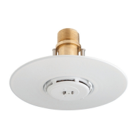
For suspended ceiling applications,
TYCO Model FSC 80 K-factor Flush
Sprinklers must be installed in accor-
dance with Steps A through F of this
procedure:
Step A Step CStep B
Step EStep D
Step F