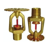
TFP810
Page 3 of 6
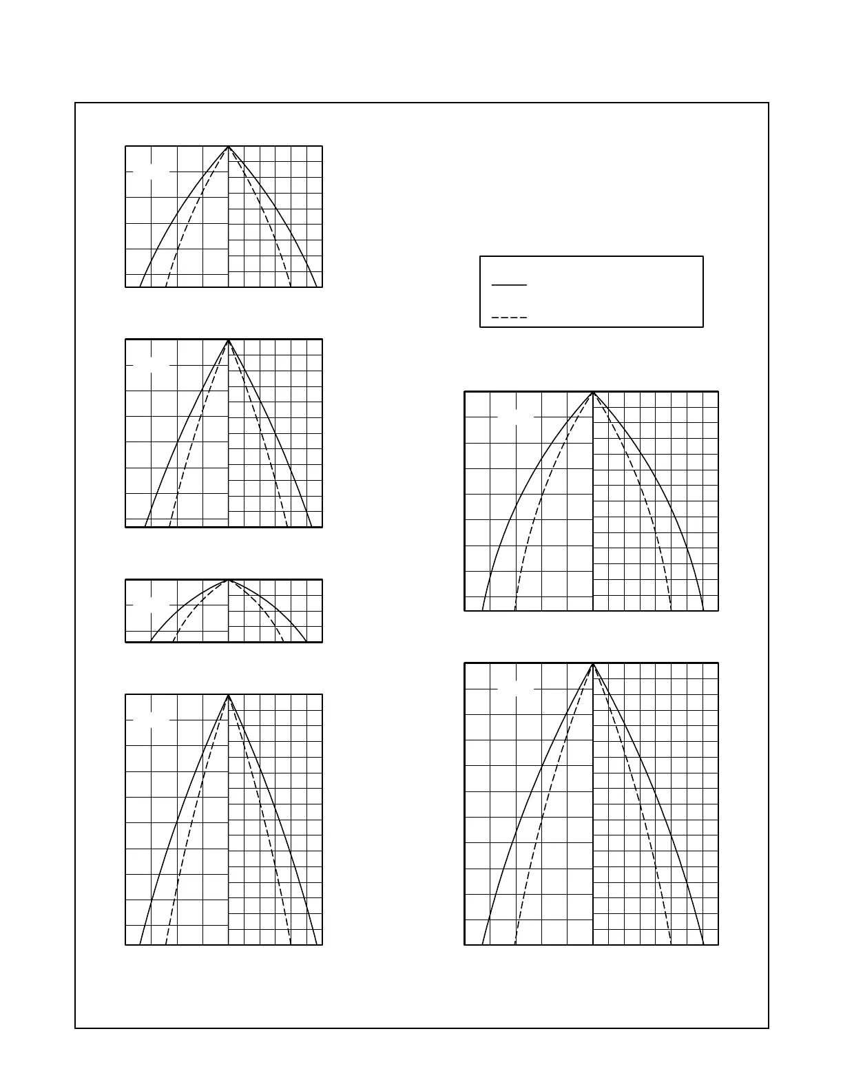
FIGURE 3 — PART 1 of 2
WATER DISTRIBUTION DESIGN DATA
DESIGN SPRAY PROFILE (S/2)
OVERALL SPRAY PATTERN
4
2,0
6
2,0
3,0
4,0
14
10
12
8
5,0
3,0
4,0
2,0
1,0
0
1,0 0 2
2
4
46
0
8
FEETMETRES
2,0 1,0
1,0
0
20
METRES FEET
6
14
18
16
10
12
8
2
4
0
68
2,0
0
2,0
1,0
8
0
4
6
2
FEETMETRES
1,0 0246
F822
(RADIAL DISTANCE)
1.
NOTES:
Data applies to a maximum wind condition of 15 MPH (24 km/h).
Data applies to a residual (flowing) pressure range at the nozzle
inlet of 30 to 60 psi (2,1 to 4,1 bar). (For pressures up to 175 psi
2.
(12,1 bar) consult Tyco Fire & Building Products Technical Services.)
unchanged over the maximum recommended axial distance and
the residual (flowing) pressure range of 30 to 60 psi (2,1 to 4,1 bar).
The shapes of the Design Spray Profiles remain essentially3.
DATA KEY
4
8
6
2
0
FEET
02462,0
METRES
1,0
2,0
1,0
0
4
2
0
FEET
02462,0
METRES
1,0
1,0
0
4
8
6
2
0
FEET
02462,0
METRES
1,0
2,0
1,0
0
3,0
4,0
16
14
12
10
3,0
10
12
AXIAL DISTANCE FROM
NOZZLE, FEET
NOZZLE, METERS
AXIAL DISTANCE FROM
AXIAL DISTANCE FROM
NOZZLE, FEET
NOZZLE, METERS
AXIAL DISTANCE FROM
AXIAL DISTANCE FROM
NOZZLE, FEET
NOZZLE, METERS
AXIAL DISTANCE FROM
AXIAL DISTANCE FROM
NOZZLE, FEET
NOZZLE, METERS
AXIAL DISTANCE FROM
AXIAL DISTANCE FROM
NOZZLE, METERS
AXIAL DISTANCE FROM
NOZZLE, METERS
AXIAL DISTANCE FROM
NOZZLE, FEET
AXIAL DISTANCE FROM
NOZZLE, FEET
F824
F826
F828
F832
F834
 Loading...