Installation
Mulsifyre Nozzles must be installed in
accordance with the following instruc-
tions:
NOTE
A leak tight 3/4 inch NPT nozzle joint
should be obtained with a torque of 10
to 20 ft.lbs. (13,4 to 26,8 Nm). A maxi-
mum of 30 ft.lbs. (40,7 Nm) of torque
is to be used to install nozzles with 3/4
NPT connections. Higher levels of
torque may distort the nozzle inlet and
cause leakage or impairment of the
nozzle.
Step 1. With pipe thread sealant ap-
plied to the pipe threads, hand tighten
the nozzle into the nozzle fitting.
Step 2. Tighten the nozzle into the
nozzle fitting using an adjustable cres-
cent wrench. With reference to Figure
1 the adjustable crescent wrench is to
be applied to the wrench flats.
REPLACEMENT DUST CAPS
When replacement Dust Caps are in-
stalled, there is to be a minimum of 5
inches (125 mm) of Wire (Ref. Figure
2) between where the Wire is looped
around the nozzle thread relief and
attached to the Dust Cap. The mini-
mum length of 5 inches (125 mm) will
help to assure that there will be an
unrestricted flow from the nozzle outlet
during operation.
Care and
Maintenance
The Mulsifyre Nozzles must be main-
tained and serviced in accordance
with the following instructions:
NOTE
Before closing a fire protection system
main control valve for maintenance
work on the fire protection system that
it controls, permission to shut down
the affected fire protection system
must be obtained from the proper
authorities and all personnel who may
be affected by this action must be no-
tified.
Mulsifyre Nozzles must never be
painted, plated, coated or altered in
any way after leaving the factory; oth-
erwise, the spray performance may be
impaired.
Care must be exercised to avoid dam-
age to the nozzles - before, during,
and after installation. Nozzles dam-
aged by dropping, striking, wrench
twist/slippage, or the like, must be re-
placed.
Frequent visual inspections are rec-
Page4of6
TFP810
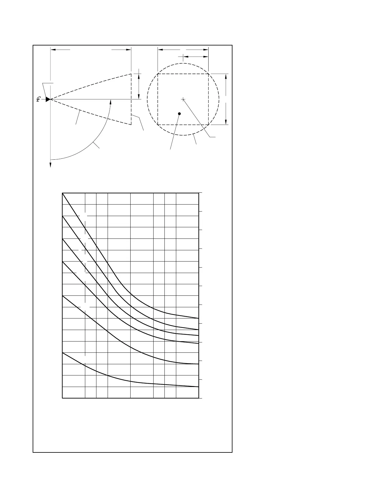
FIGURE 3 — PART 2 of 2
WATER DISTRIBUTION DESIGN DATA
AXIAL DISTANCE S
S/2
S/2
S
NOZZLE
AXIS
OVERALL
SPRAY
AREA
DESIGN
AREA
SPRAY
PLANE OF
PROTECTION
PROFILE
SPRAY
DESIGN
(90° SHOWN)
ANGLE
ORIENTATION
0° (GRAVITY)
5,0
4,0
3,0
2,0
1,0
0
0°
6
16
18
14
12
10
8
4
2
0
30° 45° 60° 90° 120° 135° 150° 180°
11
1
3
5
7
9
13
15
17
0,5
1,5
2,5
3,5
4,5
5,5
(GRAVITY)
ORIENTATION ANGLE
F826
F824
F822
F834
F828
F832
TO PLANE OF PROTECTION, FEET
MAXIMUM RECOMMENDED AXIAL DISTANCE
TO PLANE OF PROTECTION, METERS
MAXIMUM RECOMMENDED AXIAL DISTANCE
 Loading...