only necessary to design the fire sprin-
kler system, from the water supply
main to the most hydraulically remote
sprinkler. The domestic flow need not
be considered. As long as the single
sprinkler flow is equal to or greater
than 12.5 GPM when the supply pres-
sure at the main is at its minimum
expected value, the RSV-1 will auto-
matically shutoff the domestic flow.
NOTES
After the Piston has moved to the full
up position, only a small amount of
water is permitted to trickle through the
By-Pass Restriction to the Domestic
Port(Ref.Figure3).Thetrickleflow
through the By-Pass Restriction per-
mits automatic resetting of the RSV-1
Valve, without draining of the fire sprin-
kler system, after a sprinkler operation
or test. When the Manual Domestic
Shutoff Valve is closed, the By-Pass
Restriction allows the Supply and Do-
mestic Port pressures to equalize and
the Piston Assembly to move back
down to the standby position. The
maximum flow rate through the By-
Pass Restriction, when the RSV-1
Valve is in the operated position is less
than 1/4 GPM (0,9 LPM) for a typical
residual (flowing) pressure of 40 psi
(2,8 bar) at the inlet. Consequently, it
is not necessary to take into account
the trickle flow through the RSV-1
Valve By-Pass Restriction, into the do-
mestic system, when performing hy-
draulic design calculations for the fire
sprinkler system.
Installation
NOTE
A fire sprinkler water supply connec-
tion to a public water supply is usually
subject to local regulations concerning
metering and backflow prevention re-
quirements. Consult with the local
water authorities concerning local re-
quirements which may apply to the
arrangement of these components in
the fire sprinkler system water supply.
Figure 1 illustrates a typical arrange-
ment using the Model RSV-1 Residen-
tial Domestic Shutoff Valve. The ar-
rangement may need to be modified to
meet the requirements of the authority
having jurisdiction; however, the
Model RSV-1 Residential Domestic
Shutoff Valve must be installed in ac-
cordance with the following criteria:
Step 1. TheRSV-1Valveistobein-
stalled vertically with the Supply Port
at the bottom, the Fire Sprinkler Port at
the top, and the Domestic Port at the
side. It is recommended that a suitable
clamp be installed along the water
supply riser piping, to provide support
for the weight of the RSV-1 Valve.
NOTE
The maximum water supply service
lineistobe1inch(DN25).
Step 2. The water supply to the RSV-1
Valvemustbefreeofcontaminants
and particles of a size greater than 1/8
inch (3,2 mm).
Step 3. The RSV-1 is to be installed so
that the arrows cast on the Body point
in the direction of flow.
Step 4. A Domestic Control Valve is to
be located between the RSV-1 Valve
and the domestic system. The inlet to
the Domestic Control Valve is to be
located within 12 inches of the Domes-
ticPortoftheRSV-1Valve.
Step 5. The Drain and Flow Test Con-
nection (Ref. Figure 1) is recom-
mended to be minimum 1/2 inch
(DN15) for systems per NFPA 13D.
Step 6. An Alarm Test Connection with
a test orifice equal to or less than the
smallest K-factor sprinkler in the sys-
tem is to be located downstream of the
Waterflow Detector.
Step 7. Apply pipe thread sealant
sparingly only to the male pipe threads
which are to be assembled to the three
ports of the RSV-1 Valve. The use of a
Teflon* based pipe thread sealant is
recommended.
Page4of6
TFP980
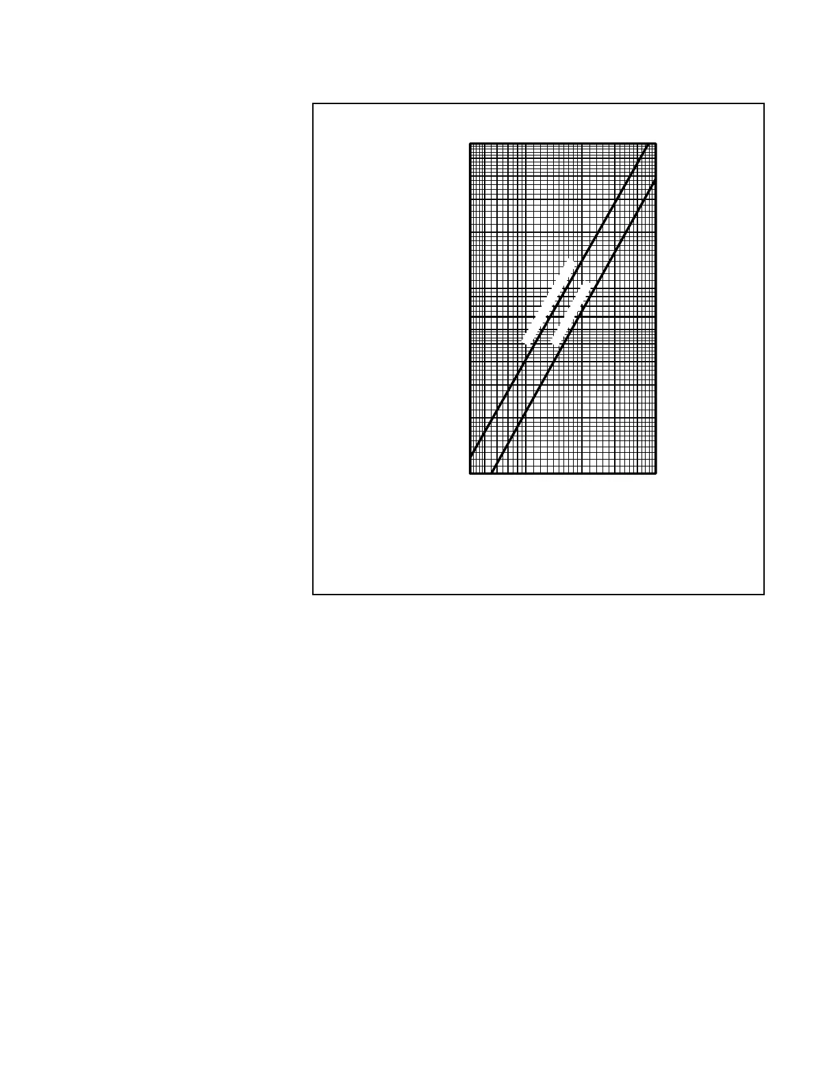
FIGURE 4
NOMINAL PRESSURE LOSS VERSUS FLOW
FLOW RATE IN GALLONS PER MINUTE (GPM)
NOMINAL PRESSURE DROP IN POUNDSPERSQUAREINCH(PSI)
2.0
0.4
0.1
0.2
0.3
0.9
0.6
0.5
0.8
0.7
1.0
3.0
4.0
6.0
5.0
56 1087 9 20 30 40 50
FIRE SPRINKLER PORT
DOMESTIC PORT
 Loading...