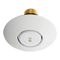
Guide Pin Housing . . . . . . Bronze
Guide Pins . . . . . . Stainless Steel
SupportCup .......... Steel
CoverPlate..........Copper
Retainer ............Brass
Cover Plate Ejection Spring . . . . .
............StainlessSteel
†DuPont Registered Trademark
Operation
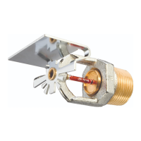
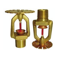
When exposed to heat from a fire, the
Cover Plate, which is normally sol-
dered to the Support Cup at three
points, falls away to expose the Sprin-
kler Assembly. At this point the Deflec-
tor supported by the Arms drops down
to its operated position. The fusible
link of the Sprinkler Assembly is com-
prised of two link halves that are sol-
dered together with a thin layer of sol-
der. When the rated temperature is
reached, the solder melts and the two
link halves separate allowing the sprin-
kler to activate and flow water.
Design
Criteria
The Series LFII (TY2596) Residential
Concealed Pendent Sprinklers are UL
and C-UL Listed for installation in ac-
cordance with the following criteria.
NOTE
When conditions exist that are outside
the scope of the provided criteria, refer
to the Residential Sprinkler Design
Guide TFP490 for the manufacturer’s
recommendations that may be accept-
able to the Authority Having Jurisdic-
tion.
System Type. Only wet pipe systems
may be utilized.
Hydraulic Design. The minimum re-
quired sprinkler flow rate for systems
designed to NFPA 13D or NFPA 13R
are given in Table A as a function of
temperature rating and the maximum
allowable coverage areas. The sprin-
kler flow rate is the minimum required
discharge from each of the total
number of “design sprinklers” as
specified in NFPA 13D or NFPA 13R.
For systems designed to NFPA 13, the
number of design sprinklers is to be
the four most hydraulically demanding
sprinklers. The minimum required dis-
charge from each of the four sprinklers
is to be the greater of the following:
• The flow rates given in Table A for
NFPA 13D and 13R as a function of
temperature rating and the maxi-
mum allowable coverage area.
• A minimum discharge of 0.1 gpm/sq.
ft. over the “design area” comprised
of the four most hydraulically de-
manding sprinklers for the actual
coverage areas being protected by
the four sprinklers.
Obstruction To Water Distribution.
Locations of sprinklers are to be in
accordance with the obstruction rules
of NFPA 13 for residential sprinklers.
Operational Sensitivity. The sprin-
klers are to be installed relative to the
ceiling mounting surface as shown in
Figure 3.
Sprinkler Spacing. The minimum
spacing between sprinklers is 8 feet
(2,4 m). The maximum spacing be-
tween sprinklers cannot exceed the
length of the coverage area (Ref. Ta-
ble A) being hydraulically calculated
(e.g., maximum 12 feet for a 12 ft. x
12 ft. coverage area, or 20 feet for a 20
ft. x 20 ft. coverage area).
Installation
The Series LFII (TY2596) must be in-
stalled in accordance with the follow-
ing instructions:
NOTES
Damage to the fusible Link Assembly
during installation can be avoided by
handling the sprinkler by the frame
arms only (i.e., do not apply pressure
to the fusible link Assembly).
A leak tight 1/2 inch NPT sprinkler joint
should be obtained with a torque of 7
to 14 ft.lbs. (9,5 to 19,0 Nm). A maxi-
Page2of4
TFP440
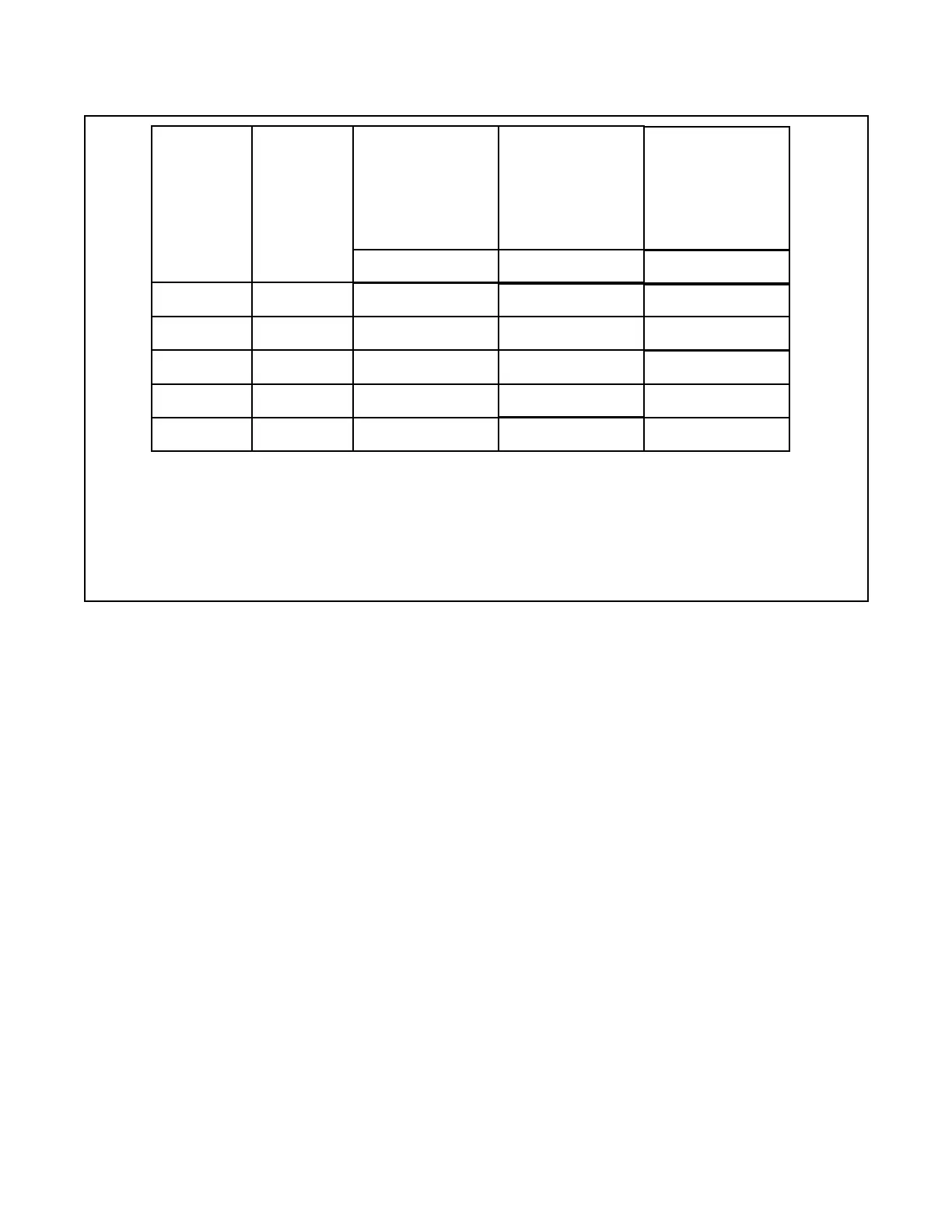
(a) For coverage area dimensions less than or between those indicated, it is necessary to use the minimum required flow for the
next highest coverage area for which hydraulic design criteria are stated.
(b) Requirement is based on minimum flow in GPM (LPM) from each sprinkler. The associated residual pressures are calculated
using the nominal K-factor. Refer to Hydraulic Design Criteria Section for details.
TABLE A
NFPA 13D AND NFPA 13R WET PIPE HYDRAULIC DESIGN CRITERIA
FOR THE SERIES LFII (TY2596) RESIDENTIAL CONCEALED PENDENT SPRINKLER
12 x 12
(3,7 x 3,7)
Maximum
Coverage
Area
(a)
Ft. x Ft.
(m x m)
Minimum Flow
(b)
and
Residual Pressure
For Horizontal Ceiling
(Max. 2 Inch Rise
for 12 Inch Run)
14 x 14
(4,3 x 4,3)
16 x 16
(4,9 x 4,9)
18 x 18
(5,5 x 5,5)
20 x 20
(6,1 x 6,1)
14 GPM (53,0 LPM)
11.1psi(0,77bar)
16 GPM (60,6 LPM)
14.5psi(1,00bar)
20 GPM (75,7 LPM)
22.7psi(1,57bar)
24 GPM (90,8 LPM)
32.7psi(2,25bar)
160°F/71°C
Sprinkler
13 GPM (49,2 LPM)
9.6 psi (0,66 bar)
12
(3,7)
14
(4,3)
16
(4,9)
18
(5,5)
20
(6,1)
Maximum
Spacing
Ft.
(m)
Minimum Flow
(b)
and
Residual Pressure
For Sloped Ceiling
(Greater Than 2 Inch
Rise Up To
Max. 4 Inch Rise
for 12 Inch Run)
160°F/71°C
Sprinkler
18 GPM (68,1 LPM)
18.4psi(1,27bar)
18 GPM (68,1 LPM)
18.4psi(1,27bar)
18 GPM (68,1 LPM)
18.4psi(1,27bar)
Minimum Flow
(b)
and
Residual Pressure
For Sloped Ceiling
(Greater Than 4 Inch
Rise Up To
Max. 8 Inch Rise
for 12 Inch Run)
160°F/71°C
Sprinkler
18 GPM (68,1 LPM)
18.4psi(1,27bar)
18 GPM (68,1 LPM)
18.4psi(1,27bar)
18 GPM (68,1 LPM)
18.4psi(1,27bar)
N/A
N/A
20 GPM (75,7 LPM)
22.7psi(1,57bar)
26 GPM (98,4 LPM)
38.3psi(2,64bar)
 Loading...