mum of 21 ft.lbs. (28,5 Nm) of torque
is to be used to install sprinklers.
Higher levels of torque may distort the
sprinkler inlet with consequent leak-
age or impairment of the sprinkler.
Do not attempt to compensate for in-
sufficient adjustment in an Escutcheon
Plate by under- or over-tightening the
Sprinkler. Readjust the position of the
sprinkler fitting to suit.
Step 1. The sprinkler must only be
installed in the pendent position and
with the centerline of the sprinkler per-
pendicular to the mounting surface.
Step 2. Remove the Protective Cap.
Step 3. With pipe thread sealant ap-
plied to the pipe threads, and using
the W-Type 18 Wrench shown in Fig-
ure 2, install and tighten the Sprink-
ler/Support Cup Assembly into the fit-
ting. The W-Type 18 Wrench will
accept a 1/2 inch ratchet drive.
TFP440
Page 3 of 4
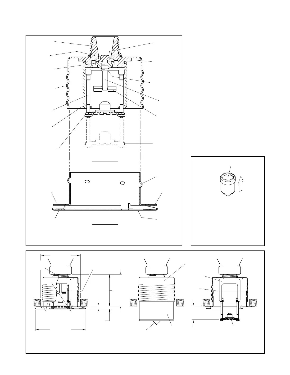
FIGURE 1
SERIES LFII (TY2596) RESIDENTIAL
CONCEALED PENDENT SPRINKLER
FIGURE 3
SERIES LFII (TY2596) RESIDENTIAL CONCEALED PENDENT SPRINKLER
INSTALLATION DIMENSIONS / PROTECTIVE CAP / ACTIVATED DEFLECTOR
FIGURE 2
W-TYPE 18
SPRINKLER WRENCH
(81,0 mm)
3-3/16" DIA.
1/2"
NPT
(63,5 mm)
2-1
2" DIA.
MOUNTING
SURFACE
(4,8 mm)
3/16"
1/8" GAP
(3,2 mm)
FITTING
SPRINKLER
FACE OF
1/2" (12,7 mm)
1" (25,4 mm)
TIP OPERATED POSITION
DEFLECTOR IN
1/2" (12,7 mm)
ADJUSTMENT
THREADED
SPRINKLER-
SUPPORT CUP
ASSEMBLY
OPERATED
SPRINKLER
1-15/16"±1/4"
±6,4 mm)
(49,2 mm
SPRINKLER-
SUPPORT CUP
ASSEMBLYASSEMBLY
COVER-
RETAINER
COVER
PLATE
RETAINER
DISPOSABLE
PROTECTIVE CAP
PLATE
COVER
EJECTION
SPRING
DIMPLES
WITH THREAD
RETAINER
ASSEMBLY
SEALING
COMPRESSION
SCREW
POSITION)
(OPERATED
DEFLECTOR
FLUSH WITH
SURFACE IS
SUPPORT CUP
UNTIL MOUNTING
THREAD INTO
SOLDER
TAB
CEILING
DEFLECTOR
CAP
COVER PLATE/RETAINER
ASSEMBLY
SPRINKLER/SUPPORT CUP
ASSEMBLY
(1/2" NPT)
BODY
AREA
WRENCHING
SPRINKLER
SADDLE
ROLL FORMED
THREADS
CUP WITH
SUPPORT
ELEMENT
SOLDER LINK
LEVER
GUIDE
PIN
HOUSING
GUIDE PIN
RECESS
WREN
H
WITH SPRINKLER
ENGAGEMENT
IN TO ENSURE
WREN
HIN
AREA
PUSH WRENCH