Design
Criteria
The Series TY-FRB, 5.6 K-factor Up-
right and Pendent Intermediate Level
Sprinklers are intended for fire pro-
tection systems designed in accor-
dance with the standard installation
rules recognized by the applicable
Listing or Approval agency (e.g., UL
Listing is based on the requirements
of NFPA 13, and FM Approval is based
on the requirements of FM’s Loss Pre-
vention Data Sheets).
Installation
The Series TY-FRB, 5.6 K-factor Up-
right and Pendent Intermediate Level
Sprinklers must be installed in accor-
dance with this section:
General Instruction
Do not install any bulb type sprin-
kler if the bulb is cracked or there is
a loss of liquid from the bulb. With the
sprinkler held horizontally, a small air
bubble should be present. The diam-
eter of the air bubble is approximately
1/16 inch (1,6 mm) for the 135°F (57°C)
to 3/32 inch (2,4 mm) for the 286°F
(141°C) temperature ratings.
A leak tight 1/2 inch NPT sprinkler
joint should be obtained with a torque
of 7 to 14 ft.-lbs. (9,5 to 19,0 Nm).
Higher levels of torque may distort the
sprinkler inlet and cause leakage or
impairment of the sprinkler.
Upright Sprinklers
The Series TY-FRB Intermediate Lev-
el Upright Sprinklers must be installed
in accordance with the following
instructions.
Step 1. With pipe thread sealant ap-
plied to the pipe threads, hand tighten
the sprinkler into the sprinkler fitting.
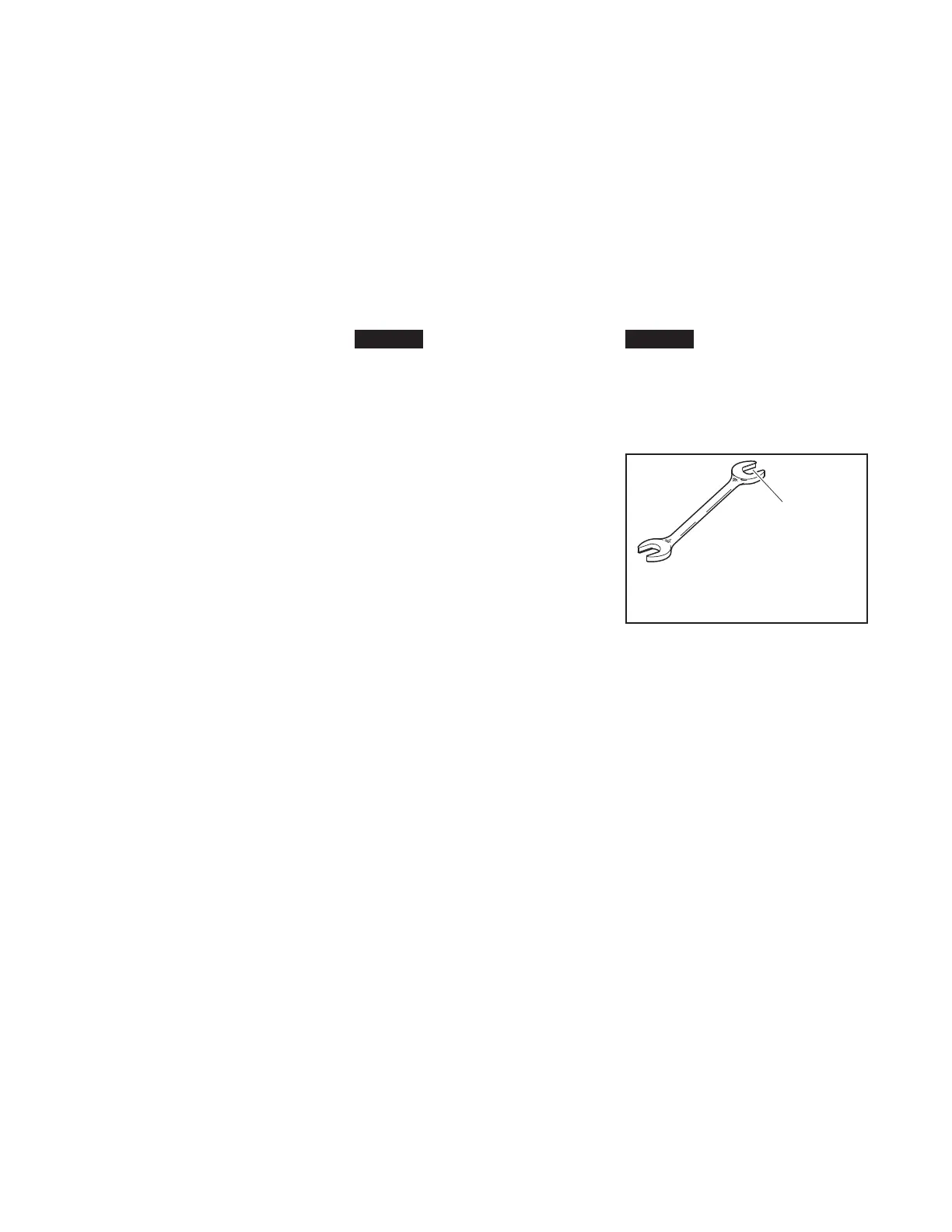
Step 2. Tighten the sprinkler into the
sprinkler fitting using only the W-Type
6 Sprinkler Wrench (Ref. Figure 5).
With reference to Figure 1, the W-Type
6 Sprinkler Wrench is to be applied to
the wrench flats.
Step 3. Mount the Model G1/S1
Guard with Shield on the sprinkler.
With the Clips loose, spread the two
halves of the Sprinkler Guard enough
to pass by the sprinkler deflector from
the side.
Step 4. Spread the two halves of
the Sprinkler Base Plates enough to
pass over the sprinkler Thread Relief
portion of the sprinkler. (Refer to
Figure 1.)
Step 5. With the Sprinkler Guard po-
sitioned on the Thread Relief portion
of the sprinkler, engage the Bars with
Clips from opposing Guard Halves,
then slide the Clips up until they are
seated against the Base Plates, com-
pleting the installation as shown in
Figure 1 and 4.
NOTE: To help assist with the sliding
of the Clips, use the Guard Installation
Tool as shown in Figure 4. Additional-
ly, pliers can be used to facilitate the
final seating of the Clips.
NOTICE
The Clips must seat against the Base
Plates to be fully seated in order to
complete the installation. The Model
G1/S1 Guard with Shield may be lo-
cated in any position relative to the
sprinkler frame arms.
Pendent Sprinklers
The Series TY-FRB Intermediate Lev-
el Pendent Sprinklers must be in-
stalled in accordance with the follow-
ing instructions.
Step A. Thread the S2 Shield on to
the sprinkler threads with the stamped
markings toward the deflector and
just to the end of the threads. The fi-
nal assembly step is easier to accom-
plish if the Shield is not disengaged by
continuing to turn the Shield past the
threads.
Step B. Roll the O-Ring over the
sprinkler threads until it seats against
the Shield.
Step C. With pipe thread sealant ap-
plied to the pipe threads, hand tighten
the sprinkler into the sprinkler fitting.
Step D. Tighten the sprinkler into the
sprinkler fitting using only the W-Type
6 Sprinkler Wrench (Ref. Figure 5).
With reference to Figure 2 or 3, the W-
Type 6 Sprinkler Wrench is to be ap-
plied to the wrench flats.
Step E. Rotate the S2 Shield clock-
wise (looking up) so that it slightly
compresses the O-Ring between the
Shield and sprinkler fitting.
Note: Installation of the S2 Shield only
is completed at this point (Ref. Figure
3). If installing a G1 Guard, proceed to
the next step.
Step F. Mount the Model G1 Guard
on the sprinkler. With the Clips loose,
spread the two halves of the Sprinkler
Guard enough to pass by the sprinkler
deflector from the side.
Step G. Spread the two halves of
the Sprinkler Base Plates enough to
pass over the sprinkler Thread Relief
portion of the sprinkler. (Refer to
Figure 2.)
Step H. With the Sprinkler Guard po-
sitioned on the Thread Relief portion
of the sprinkler, engage the Bars with
Clips from opposing Guard Halves,
then slide the Clips up until they are
seated against the Base Plates, com-
pleting the installation as shown in
Figure 2 and 4.
NOTE: To help assist with the sliding
of the Clips, use the Guard Installation
Tool as shown in Figure 4. Additional-
ly, pliers can be used to facilitate the
final seating of the Clips.
NOTICE
The Clips must seat against the Base
Plates to be fully seated in order to
complete the installation. The Model
G1 Guard may be located in any po-
sition relative to the sprinkler frame
arms.
TFP357
Page 4 of 6
(USE ONLY
END "A")
FIGURE 5
W-TYPE 6 SPRINKLER
WRENCH

 Loading...