Installation
Installation instructions are provided in
the following subsections:
• Sprinkler Only
• Sprinkler With Guard
• Sprinkler With Shield
• Sprinklers With Guard & Shield
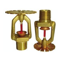
SPRINKLER ONLY
The Model TY-FRFS, TY-FS Special,
and TY-FS Sprinklers must be in-
stalled in accordance with the follow-
ing instructions:
NOTES
Do not install any bulb type sprinkler if
the bulb is cracked or there is a loss of
liquid from the bulb. With the sprinkler
held horizontally, a small air bubble
should be present. The diameter of the
air bubble is approximately 1/16 inch
(1,6 mm) for the 135°F/57°C to 3/32
inch (2,4 mm) for the 360°F/182°C
temperature ratings.
A leak tight 1/2 inch NPT sprinkler joint
should be obtained with a torque of 7
to 14 ft.lbs. (9,5 to 19,0 Nm). A maxi-
mum of 21 ft. lbs. (28,5 Nm) of torque
may be used to install sprinklers with
1/2 NPT connections. A leak tight 3/4
inch NPT sprinkler joint should be ob-
tained with a torque of 10 to 20 ft.lbs.
(13,4 to 26,8 Nm). A maximum of 30
ft.lbs. (40,7 Nm) of torque is to be used
to install sprinklers with 3/4 NPT con-
nections. Higher levels of torque may
distort the sprinkler inlet and cause
leakage or impairment of the sprinkler.
Do not attempt to make-up for insuffi-
cient adjustment in the escutcheon
plate by under- or over-tightening the
sprinkler. Readjust the position of the
sprinkler fitting to suit.
Step 1. Pendent sprinklers are to be
installed in the pendent position, and
upright sprinklers are to be installed in
the upright position.
Step 2. With pipe thread sealant ap-
plied to the pipe threads, hand tighten
the sprinkler into the sprinkler fitting.
Step 3. Tighten the sprinkler into the
sprinkler fitting using only the W-Type
6 Sprinkler Wrench (Ref. Figure 10).
With reference to Figures 1, 2, and 3
the W-Type 6 Sprinkler Wrench is to
be applied to the wrench flats.
SPRINKLER WITH GUARD
With reference to Figure 4, the Model
G1 Guard must be installed as follows:
Step 1. TheG1Guardistobe
mounted on the sprinkler after the
sprinkler has been installed in accord-
ance with the “Sprinklers Only” sub-
section.
Step 2. With the Clips loose, first
spread the two halves of the Sprinkler
Guard just enough to pass by the
sprinkler deflector from the side. Then,
once again spread the two halves of
the Sprinkler Guard just enough to
pass over the sprinkler “thread relief”
portion of the sprinkler. (Refer to Fig-
ures 2 and 3.)
Step 3. With the Sprinkler Guard posi-
tioned on the “thread relief” portion of
the sprinkler, as applicable, engage
the Clips and then slide the Clips until
they seat against the Base to complete
the installation as shown in Figure 4.
To help assist with the sliding of the
Clips, the Guard Installation Tool may
be used as shown in Figure 9. In addi-
tion, pliers can be used to facilitate the
final seating of he Clips.
NOTES
The Clips must seat against the Base
in order to be considered fully seated
and in order to complete the installa-
tion.
The G1 may be located in any position
relative to the sprinkler frame arms.
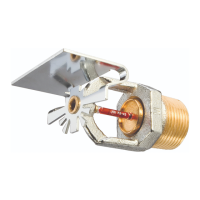
SPRINKLER WITH SHIELD
With reference to Figures 5, 6, 7, or 8,
the Model H1 or Model H2 Shield must
be installed as follows:
Step 1. Pendent sprinklers are to be
installed in the pendent position.
Step 2. With pipe thread sealant ap-
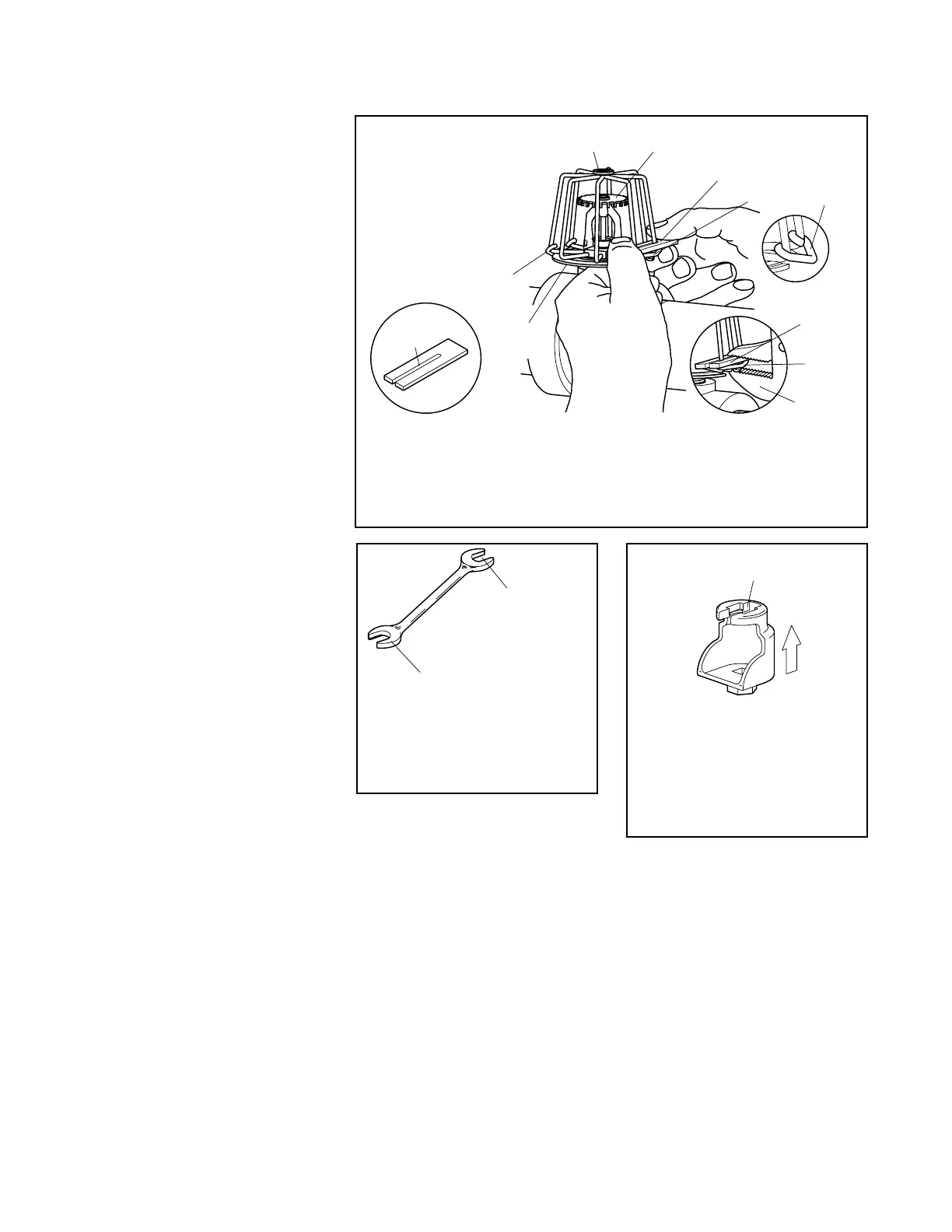
FIGURE 9
MODEL G-1 GUARD INSTALLATION PROCEDURE
WITH INSTALLATION TOOL APPLIED OVER
TOWARD BASE PLATES UNTIL FULLY ENGAGED
ADJACENT BARS, PRESS SECOND CLIP
SWIVEL CLIPS OVER
INSTALLED, CAREFULLY
AND FIT ONTO SPRINKLER
TOWARD BASE PLATES
ADJACENT BARS AND SLIDE
SPREAD BASE PLATES APART
PLATES
BASE
FIRST
CLIP INSTALLATION
TOOL (SHIPPED WITH
GUARDS)
CLIP FULLY
ENGAGED
SLOT
BAR
CLIP FULLY
ENGAGED
SECOND
A PLIER
USED
MAY BE
INSTALLATION
TOOL
CLIP
CLIP
TOOL
INSTALLATION
CLIP
CLIP
WITH SPRINKLER PROPERLY
THREAD RELIEF
UNTIL SNUG
MODEL G1
GUARD
FLAT SPRAY
SPRINKLER
FIGURE 10
W-TYPE 6 SPRINKLER
WRENCH
WRENCH RECESS
(END "A" USED FOR
ISO 7/1-R 3/8 &
WRENCH RECESS
(END "B" USED FOR
3/4" NPT MODELS
1/2" NPT MODELS)
FIGURE 11
W-TYPE 7 SPRINKLER
WRENCH
RECESS
WREN
H
WITH SPRINKLER
ENGAGEMENT
IN TO ENSURE
WREN
HIN
AREA
PUSH WRENCH
TFP635
Page 7 of 10
 Loading...