4. RELIEF VALVE (Reference)
1)GENERAL DESCRIPTION
This valve regulates the maximum pressure in
the whole hydraulic circuit.The regulated
pressure can be set with the adjust screw.
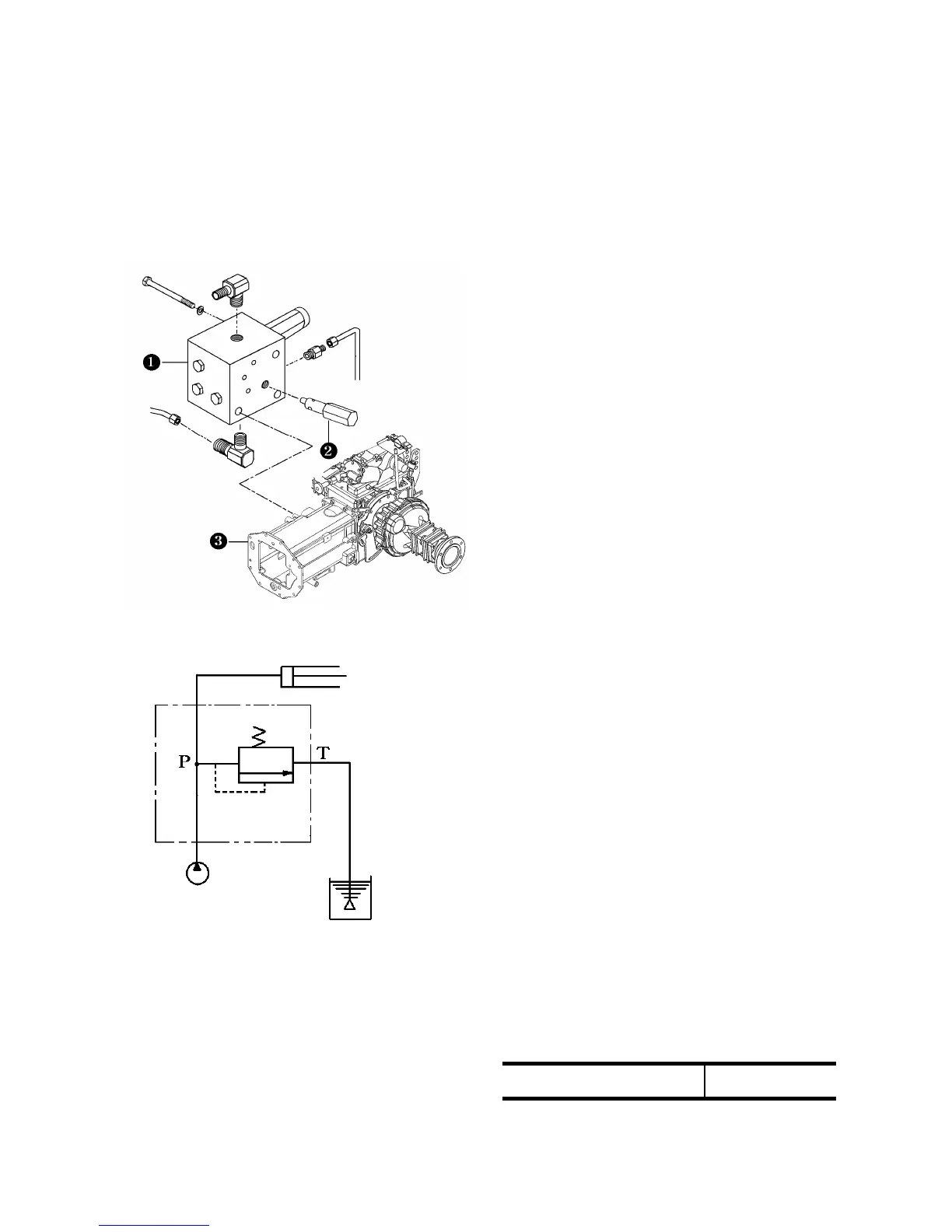
9 Relief valve in PTO solenoid V/V
2) PRECAUTIONS FOR DISASSEMBLY
AND REASSEMBLY
(1)Tightening torque of lock nut (9)5.0∼6.0
㎏f·㎠(36.2∼43.4 ft.lbs)
(2)Install seat(2)and then tap ball(3)(5/16)
lightly so as to provide tight seating.
(3)Wrap the valve threads with sealing tape
and tighten the valve up to a specified
torque of 5-6Kgf.m(36-43 ft.lbs)
(4)Before disassembly, the current
screwing-in depth of the adjust screw
should be written down or memorized for
later reference.
3) MEASUREMENT OF THE RELIEF
PRESSURE
(1)3 POINT TO TEST RELIEF PRESSURE
9 Relief valve in PTO solenoid V/V
Fig 9-10 relief valve circuit.
①Remove the plug in the delivery pipe on
the right-hand side of the transmission
case and install a compression gauge to
measure the pressure.
Keep the engine speed at 2700 rpm and
shift the position control lever at the
highest position.
②Control valve coupler.
③Remove the plug in the hyd. pump flange
and engage the pressure gauge and
measure it.
Measurement the Pressure must be done 3
times and should be set within specified
pressure.
Specified relief pressure
145 ±5 ㎏f·㎠
9-9
 Loading...