(2) Inspection
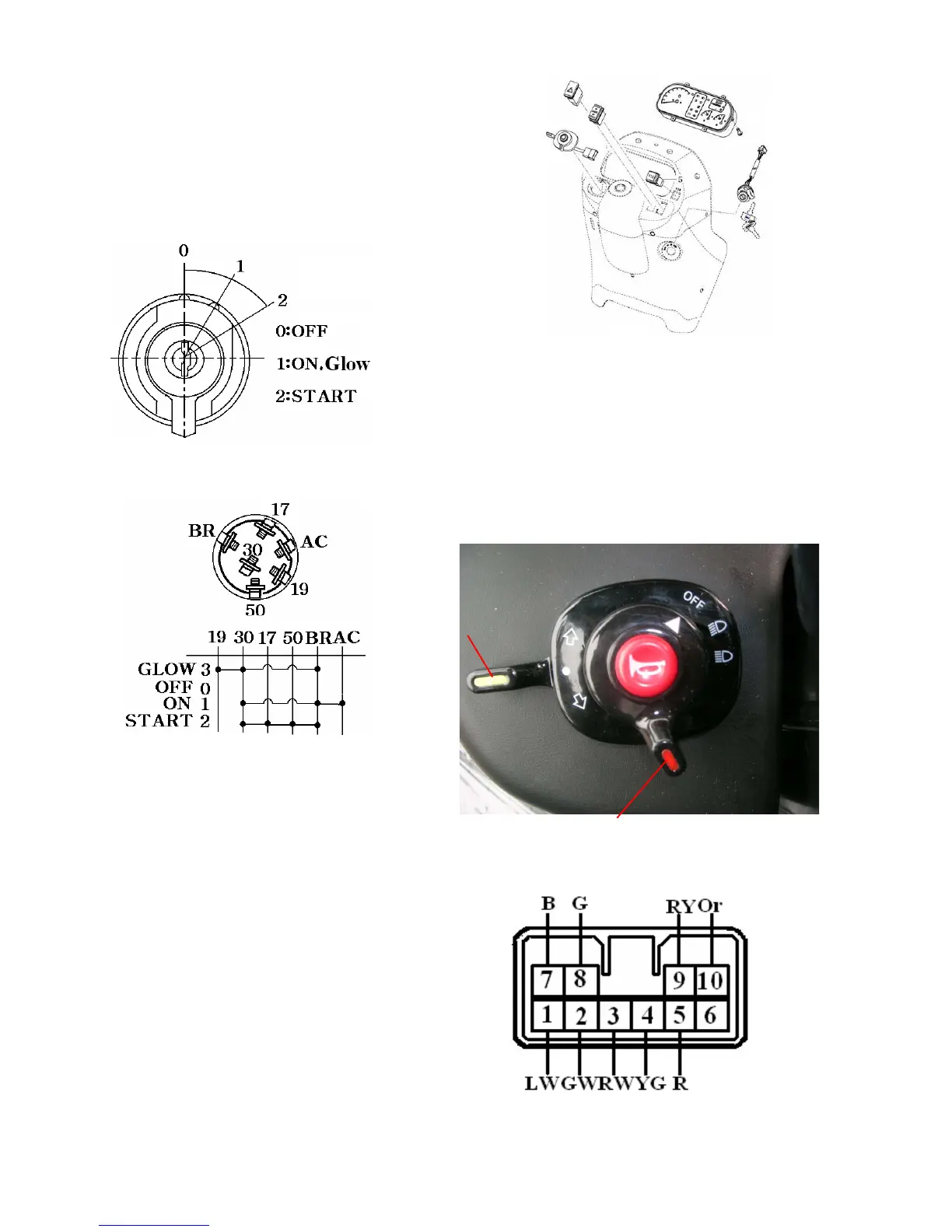
a.The main switch circuit,switching positions,
and terminals are as shown in the figures.
Check the continuity across respective
terminals referring to the switch circuit
diagram. Replace a defective switch as an
assembly
Fig.10-9
Fig.10-12
(3) Release the ring nut with a conventional
screw drive(-) and remove the combination
switch.
2) Inspection
Each switch circuit is as shown,so check each
switch for a continuity across respective
terminals with a tester.Replace a defective
switch as an assembly.
10-7
Fig.10-10
3. COMBINATION SWITCH
1) Removal
(1) Remove the meter panel
(2) Remove the light switch knob and turn
signal switch lever.
Fig.10-14 Harness socket
Fig.10-13 combination switch
Light switch
Signal switch