-Lighting
Color
code
RY
(Red /
Yellow)
R
(Red)
YG
(Yellow
/ Green)
Or
(Orange
/ red)
9 : B1*1 5 : T 4 : 1 10 : 2
OFF
**2
1
● ● ●
2
● ● ●
*1 :Terminals
**2: Switching positions
-Flasher
Color
code
G
(Green)
RW
(Red/White)
GW
(Green/White)
8 : B2*1 3 : R 2: L
1**2
● ●
Capacity 10~20A (DC12V)
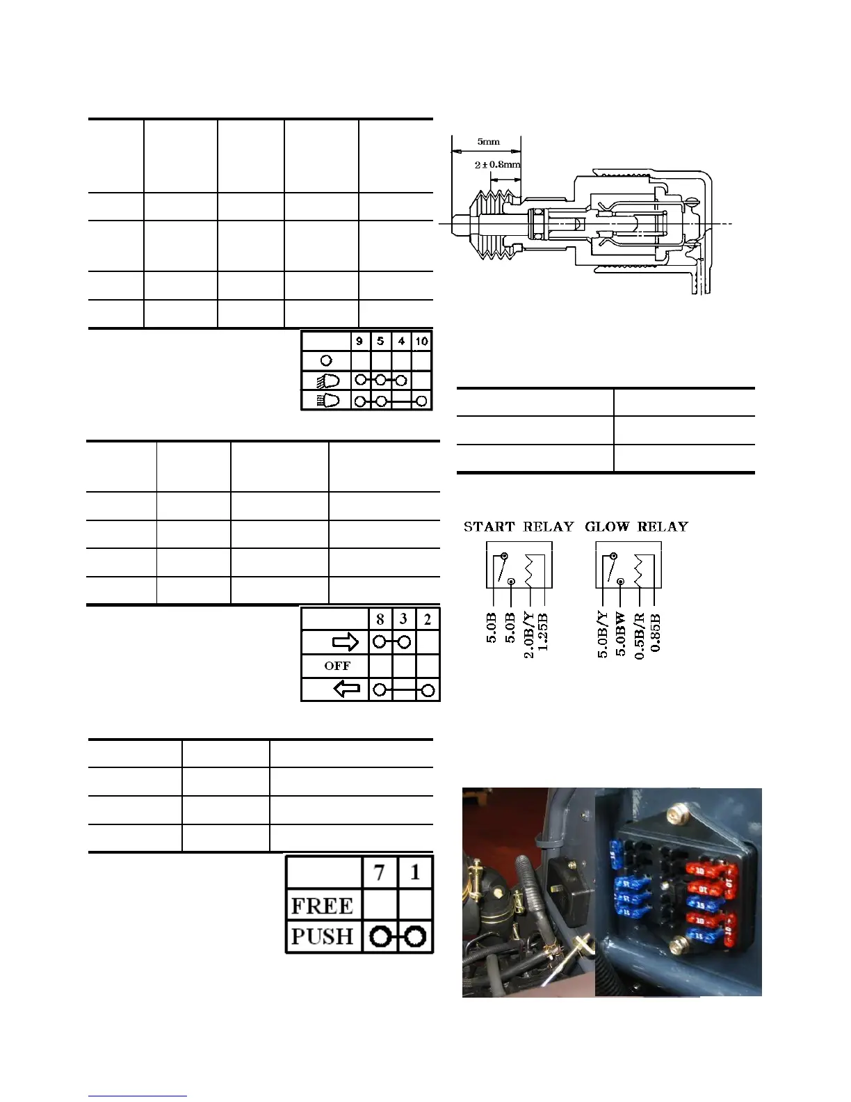
Stroke to ON
3 ±0.5mm
Total stroke 8mm
4. STOP LIGHT SWITCH
5.RELAY UNIT
Fig.10-15 Stop light switch
10-8
OFF
2
● ●
-Horn switch
*1 :Terminals
**2: Switching positions
*1 :Terminals
**2: Switching positions
Color code B (Black) LW(Light/White)
7 : B1*1 1 : H
Free**2
Push
● ●
Fig.10-16 Relay unit
6. FUSE
Fuses are installed in the main fuse box and one
for the headlights.Three fusible links are
installed to prevent the wiring from burning
due to a short circuit.
Fig.10-17 Fuse box