UBX-G7020 - Hardware Integration Manual
Design-in
GPS.G7-HW-10003 Objective Specification Page 35 of 74
b. In the field: Is the antenna connector accessible by the user?
The following subsections provide several options addressing the various questions above.
In some applications, such as GSM transceivers, interference signals may exceed the maximum power
rating of the LNA_IN input. To avoid device destruction use of external input protection is mandatory.
During assembly of end-user devices which contain passive patch antennas, an ESD discharge may occur
during production when pre-charged antennas are soldered to the GPS/GNSS receiver board. In such
cases, use of external protection in front of LNA_IN is mandatory to avoid device destruction.
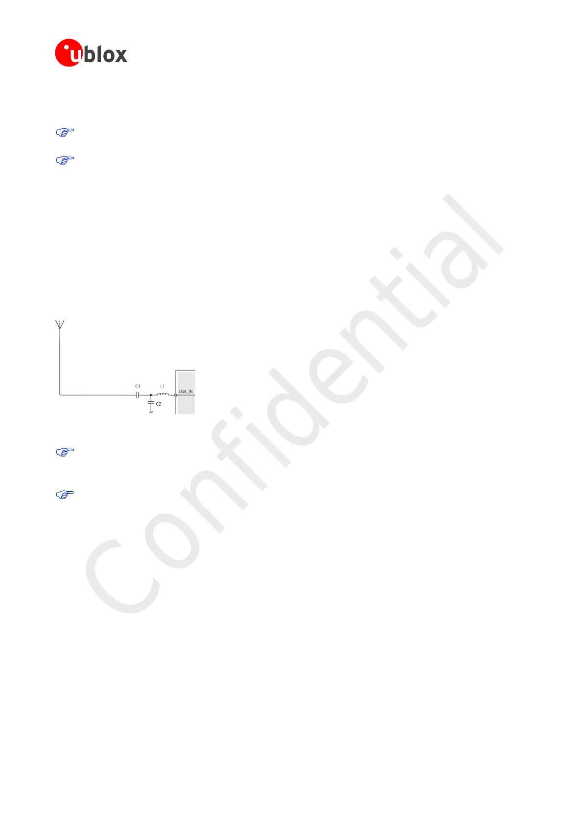
2.6.2.1 RF front-end using a passive antenna
If a passive antenna with high RHCP antenna gain and good sky view is used together with a short 50 ohm line
between antenna and receiver, the circuit in Figure 17 can be used. This provides the minimum BoM cost and
minimum board space.
Components L1 and C2 serve as input matching for the LNA input. Depending on board layout the values may
need to be adjusted to provide a 50 Ohm input impedance. Starting values are provided in sections 3.14 and
3.16, C1 is a DC block.
Figure 17: LNA input matching
ESD discharge into the RF input cannot always be avoided during assembly and / or field use with this
Circuit! To provide additional robustness an ESD protection diode, as listed in section 3.10, can be
placed at LNA_IN to GND.
There is no internal DC blocking capacitor at the LNA_IN pin. Thus when using a passive antenna with
an integral short to GND, e.g. PIF antenna, a DC blocking capacitor C1 between the antenna and
matching network is required.
2.6.2.2 External LNA for improved performance
As mentioned earlier an external LNA (U1) will improve the RF noise figure (see Figure 18 below), which results in
a better GPS/GNSS performance. Because the out-of-band gain of the external LNA (U1) will increase the
sensitivity to interference it is advisable to put an additional SAW filter (F1) between the external LNA (U1) and
the UBX-G7020 input matching network.
Components L1 and C2 serve as input matching for the LNA input. Depending on the board layout the values
need to be tuned until a 50 Ohm input impedance is achieved. Starting values are provided in Sections 3.14 and
3.16, C1 is a DC block.
 Loading...

