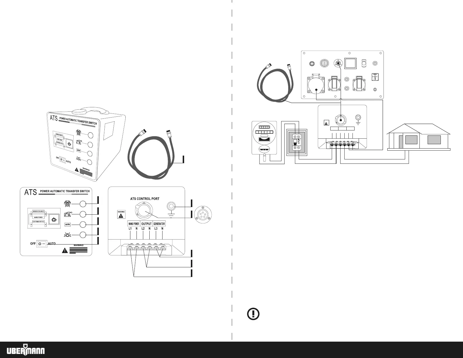
CONNECTION OF GENERATOR WITH ATS (SINGLE PHASE)
6. Grounding
7. ATS control connector between control box and generator.
8. Connection to the generator socket
9. Connection to the charging circuit
10. Commercial electrical mains connection
11. Transmitter cable for control over the ATS
AUTOMATIC TRANSFER SWITCH (ATS)
1. approximately 10 seconds. It will supply energy to the home.
2. If the supply is restored from the company, the ATS will notice this situation. It will then transfer the load to the
commercial power supply automatically, also disconnecting the power from the generator. It will then stop the
generator after 10 seconds, in order to avoid damage to the machine by sudden stop.
3. If the generator does not start in the third attempt, the "ALARM" indicator will light. Never attempt to restart the
generator to restart the ATS unless you have checked and repaired the generator. The indicator mentioned above is
only suitable for single-phase and single-voltage generators. Single-phase dual-voltage ATS generators have no alarm
indicator.
4. For single-phase dual-voltage ATS generators:
• When the commercial network is in normal operation, the ATS output voltage is equal to the input voltage
(commercial current).
• When the generator is started, due to the interruption or fall of the commercial network, the output voltage of the
ATS will be configured in the connection between the generator and the ATS. It is understood, therefore, that the
connection between these two devices will determine the output voltage of the ATS.
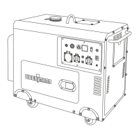
ATS "AUTOMATIC TRANSFER SWITCH"
ELECTRICAL SYSTEM FOR AUTOMATIC ON/OFF CONTROL OF THE (Fig. C).
The ATS is a system for monitoring the state of the mains, supplied by the electric company, and the electric generator
connected to its installation.
When the electrical power of the mains is interrupted, the ATS disconnects the mains from the home installation. Then,
turns on the generator and ends up connecting it to the home once it has fully started.
The objective of the system is to keep energized the electrical installation of the home that is connected to the system.
The system consists of a generator with electric start and connection to the ATS control. ATS control box and
connection cable.
ATS CONTROLS THE BOX PARTS
1. Charging indicator light energized by the commercial mains.
2. Load indicator light energized by the generator.
3. ON ATS system indicator light.
Lights when switch (5) are set to "I" (AUTO)
4. Emergency indicator light.
5. ATS system on/off switch.
1
2
3
4
5
6
7
9
8
10
11
ATS CONTROL PORT
OUTPUT
L1 L2 L3N N N
GENERATOR
MAINS POWER
WARNING!
Connect output cable to the charging circuit
Connect ATS control cable between
generator and ATS control box.
Connect with male plug to the
generator socket.
Connect mains cable
MAX. 50 A
T
ELECT
kW/hr
20187
000386
Fig. C
WARNING! Load circuit, its consumption must not exceed 45A or 4.4 KW
WARNING! The circuit breaker or thermal protection connected to the power grid to the
ATS must not exceed 50A.
63 64