SARA-G450 - System integration manual
UBX-18046432 - R08 Design-in Page 70 of 143
C1-Public
2.2.2 RTC supply (V_BCKP)
2.2.2.1 Guidelines for V_BCKP circuit design
If RTC timing is required to run for a time interval of T [s] at +25 °C when VCC supply is removed, place
a capacitor with a nominal capacitance of C [mF] at the V_BCKP pin. Choose the capacitor using the
following formula:
C [mF] = (Current Consumption [mA] x T [s] / Voltage Drop [V]
= 0.37 x T [s] for SARA-G450 modules
For example, to provide a long buffering time, a 70 mF super-capacitor (e.g. Seiko Instruments
XH414H-IV01E) can be placed at V_BCKP, with a 4.7 kΩ series resistor. This capacitor holds V_BCKP
voltage within its valid range for around 3 minutes at +25 °C, after the VCC supply is removed. The
purpose of the series resistor is to limit the capacitor charging current due to the large capacitor
specifications, and also to let a fast rise time of the voltage value at the V_BCKP pin after VCC supply
has been provided. This capacitor allows the time reference to run during battery disconnection.
1:1 scaling
R1
SARA-G450
C1
(superCap)
(a)
2
V_BCKP
D2
SARA-G450
B2
(b)
2
V_BCKP
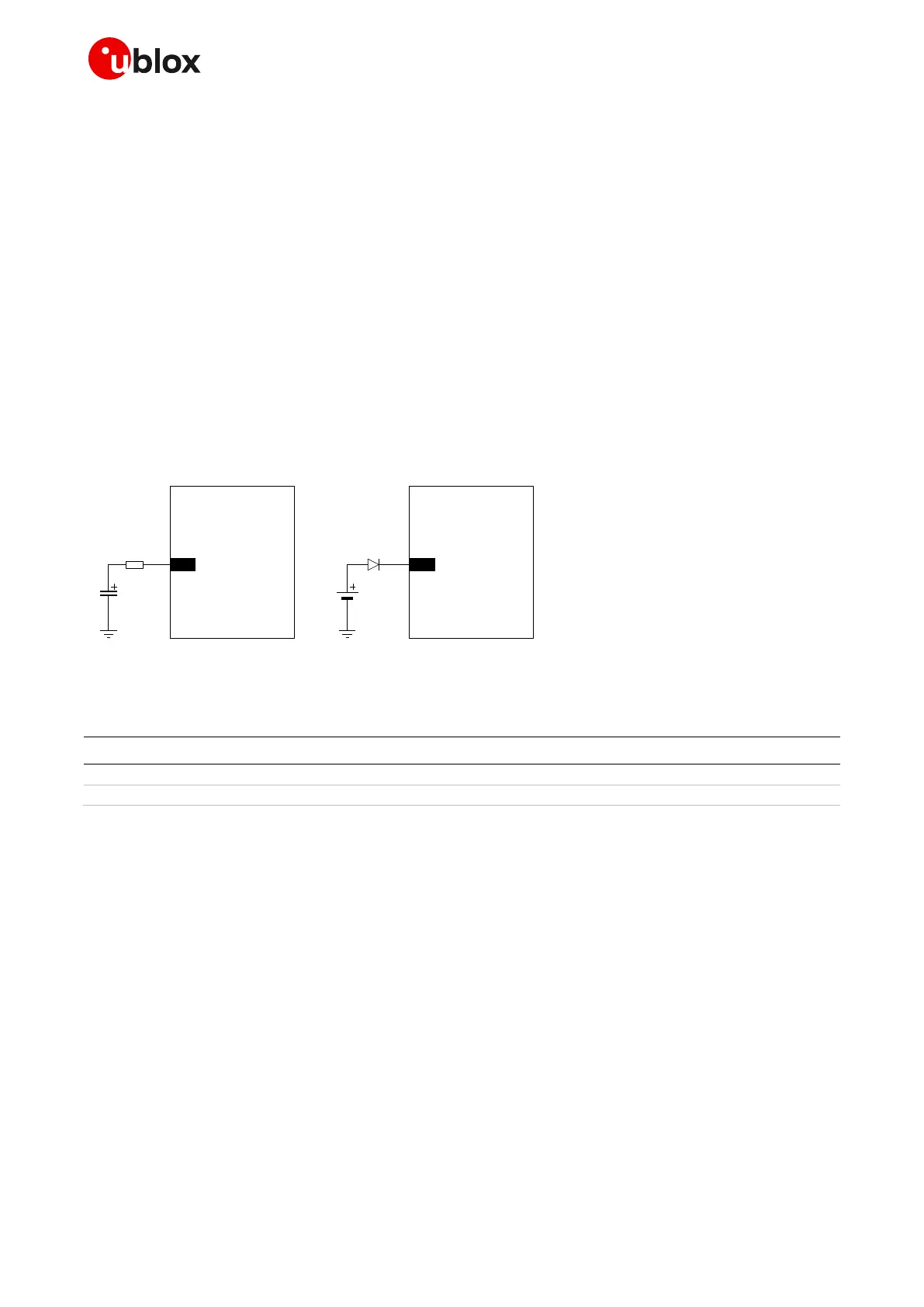
Figure 32: Real Time Clock supply (V_BCKP) application circuits: (a) using a 70 mF capacitor to let the RTC run for ~3 minutes
after VCC removal; (b) using a non-rechargeable battery
Part number - Manufacturer
4.7 k resistor 0402 5% 0.1 W
RC0402JR-074K7L - Yageo Phycomp
XH414H-IV01E - Seiko Instruments
Table 21: Examples of components for V_BCKP buffering
If a longer buffering time is required to allow the RTC time reference to run during a disconnection of
the VCC supply, then an external battery can be connected to V_BCKP pin. The battery should be able
to provide a clean nominal voltage and must never exceed the maximum operating voltage for V_BCKP
(specified in the input characteristics of the supply/power pins table in the SARA-G450 data sheet [1]).
The connection of the battery to V_BCKP should be done with a suitable series resistor for a
chargeable battery, or with an appropriate series diode for a non-rechargeable battery. The purpose
of the series resistor is to limit the battery charging current due to the battery specifications, and also
to allow a fast rise time of the voltage value at the V_BCKP pin after the VCC supply has been provided.
The purpose of the series diode is to avoid a current flow from the module V_BCKP pin to the
non-rechargeable battery.
☞ If the RTC timing is not required when the VCC supply is removed, it is not needed to connect the
V_BCKP pin to an external capacitor or battery. In this case the date and time are not updated
when VCC is disconnected. If VCC is always supplied, then the internal regulator is supplied from
the main supply and there is no need for an external component on V_BCKP.

 Loading...