SARA-G450 - System integration manual
UBX-18046432 - R08 Design-in Page 82 of 143
C1-Public
GSM / WCDMA / LTE ceiling-mount antenna with N-type(F) connector
698..960 MHz, 1575.42 MHz, 1710..2700 MHz
86 x Ø 199 mm
GSM / WCDMA / LTE pole-mount antenna with N-type(M) connector
698..960 MHz, 1710..2690 MHz
248 x Ø 24.5 mm
GSM / WCDMA low-profile adhesive-mount antenna with cable and
SMA(M) connector
824..960 MHz, 1710..2170 MHz
138 x 21 x 6 mm
Table 26: Examples of external antennas
2.4.2 Antenna detection interface (ANT_DET)
2.4.2.1 Guidelines for ANT_DET circuit design
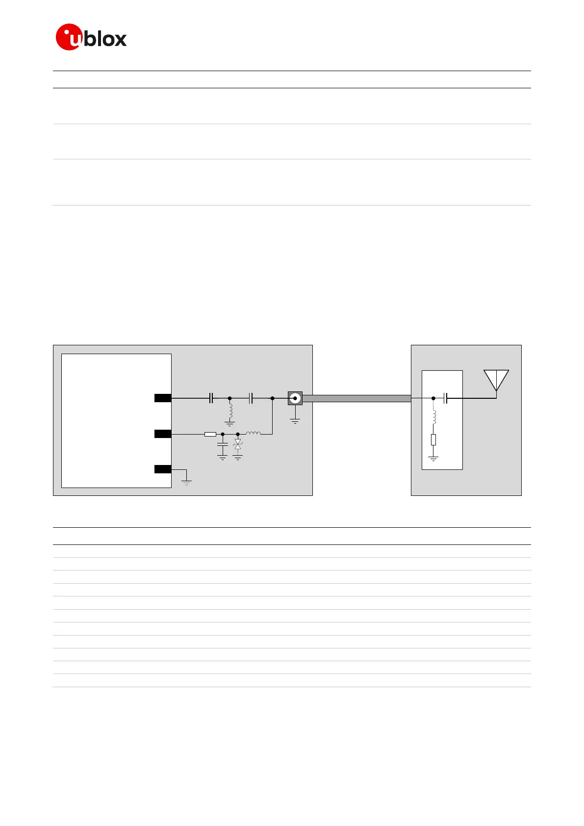
Figure 41 and Table 27 describe the recommended schematic and components for the antenna
detection circuit to be provided on the application board for the diagnostic circuit that must be
provided on the antenna assembly to achieve antenna detection functionality.
Application board
Antenna cable
SARA-G450
56ANT
62
ANT_DET
R1
C1 D1
L1
C2
J1
Z
0
= 50
Ω
Z
0
= 50
Ω
Z
0
= 50 ohm
Antenna assembly
R2
C4
L3
Radiating
element
Diagnostic
circuit
GND
L2
C3
Figure 41: Suggested schematic for antenna detection circuit on application PCB and diagnostic circuit on antenna assembly
Part number - Manufacturer
27 pF capacitor ceramic C0G 0402 5% 50 V
33 pF capacitor ceramic C0G 0402 5% 50 V
Very low capacitance ESD protection
PESD0402-140 - Tyco Electronics
68 nH multilayer inductor 0402 (SRF ~1 GHz)
10 k resistor 0402 1% 0.063 W
RK73H1ETTP1002F - KOA Speer
SMA connector 50 Pin-Through-Hole
SMA6251A1-3GT50G-50 - Amphenol
15 pF capacitor ceramic C0G 0402 5% 50 V
39 nH multilayer inductor 0402 (SRF ~1 GHz)
22 pF capacitor ceramic C0G 0402 5% 25 V
68 nH multilayer inductor 0402 (SRF ~1 GHz)
15 k resistor for diagnostic
Table 27: Suggested parts for antenna detection circuit on application PCB and diagnostic circuit on antenna assembly

 Loading...