SARA-G450 - System integration manual
UBX-18046432 - R08 Design-in Page 72 of 143
C1-Public
☞ If the V_INT supply output is not required by the customer application, the V_INT pin can be left
unconnected.
☞ It is recommended to provide on the application board a directly accessible Test-Point connected
to the V_INT pin for diagnostic purpose.
2.2.3.2 Guidelines for V_INT layout design
There are no specific layout design recommendations for V_INT output.
2.3 System functions interfaces
2.3.1 Module power-on (PWR_ON)
2.3.1.1 Guidelines for PWR_ON circuit design
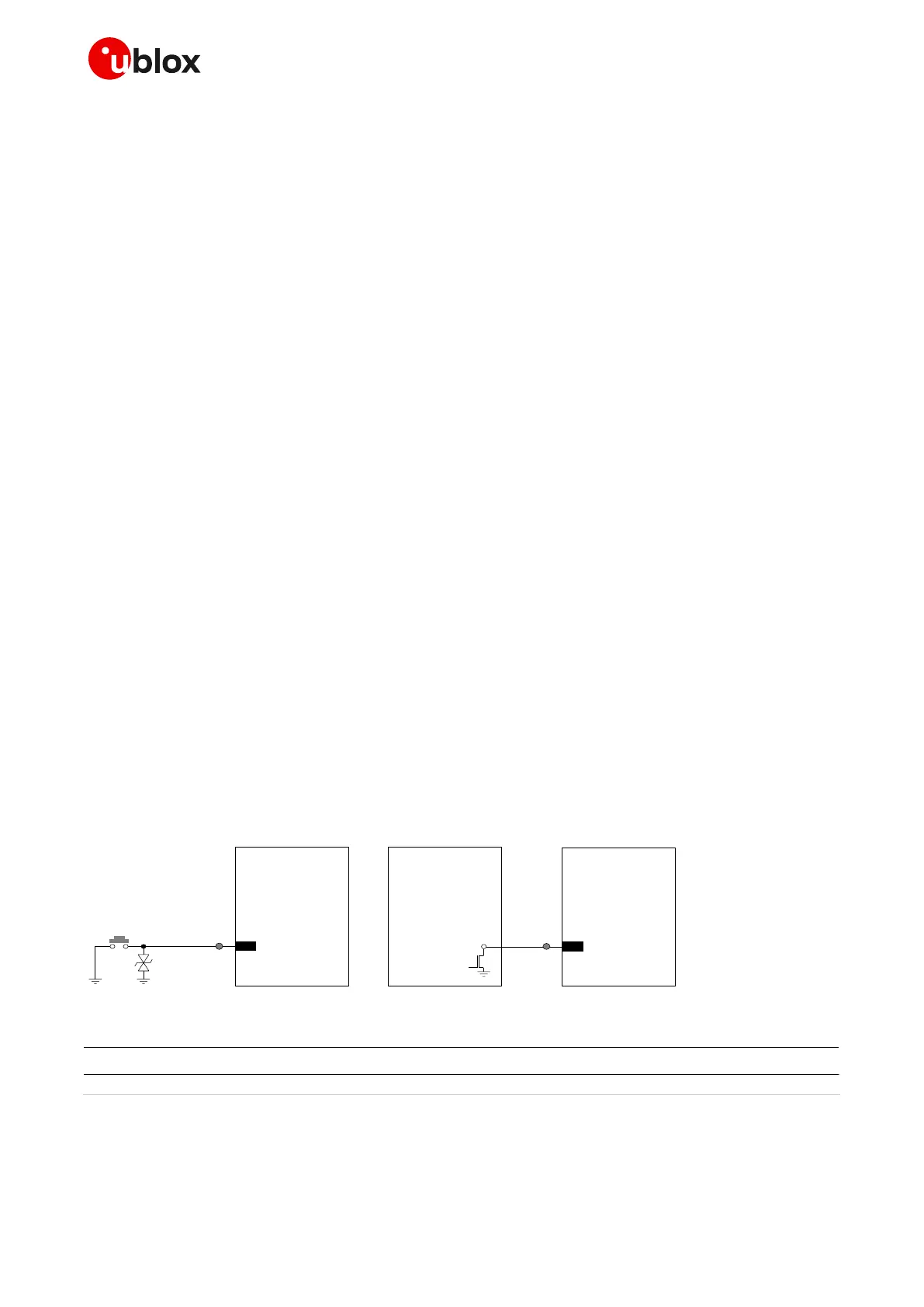
Connecting the PWR_ON input to a push button that shorts the PWR_ON pin to GND, the pin will be
externally accessible on the application device: according to EMC/ESD requirements of the
application, provide an additional ESD protection (e.g. EPCOS CA05P4S14THSG varistor array) on the
line connected to this pin, close to accessible point, as described in Figure 33 and Table 22.
☞ The ESD sensitivity rating of the PWR_ON pin is 1 kV (HBM according to JESD22-A114). A higher
protection level can be required if the line is externally accessible on the application board, e.g. if
an accessible push button is directly connected to PWR_ON pin. A higher protection level can be
achieved by mounting an ESD protection (e.g. EPCOS CA05P4S14THSG) close to accessible points
When connecting the PWR_ON input to an external device (e.g. application processor), use an open
drain output on the external device, as described in Figure 33.
A compatible push-pull output of an application processor can be used too.
The PWR_ON input voltage thresholds are different from the other generic digital interfaces of the
module: see the SARA-G450 data sheet [1] for detailed electrical characteristics.
Take care to fix the correct level in all the possible scenarios to avoid an inappropriate module
switch-on.
1:1 scaling
SARA-G450
15
PWR_ON
Power-on
push button
ESD
Open drain
output
Application
Processor
SARA-G450
15
PWR_ON
TP
TP
Figure 33: PWR_ON application circuits using a push button and an open drain output of an application processor
Part Number - Manufacturer
Varistor array for ESD protection
Table 22: Example of ESD protection for the PWR_ON application circuit
☞ It is recommended to provide on the application board a directly accessible Test-Point connected
to the PWR_ON pin for diagnostic purpose.

 Loading...