SARA-R5 series - System integration manual
UBX-19041356 - R04 System description Page 31 of 118
C1-Public
SARA-R5 series modules’ UART interface is by default configured for AT commands: the module
waits for AT command instructions and interprets all the characters received as commands to
execute. All the functionalities supported by SARA-R5 series modules can be in general set and
configured by AT commands:
• AT commands according to 3GPP TS 27.007 [6], 3GPP TS 27.005 [7], 3GPP TS 27.010 [8]
• u-blox AT commands (see the SARA-R5 series AT commands manual [2])
The UART interfaces settings can be suitably configured by AT commands (for more details, see the
SARA-R5 series AT commands manual [2]).
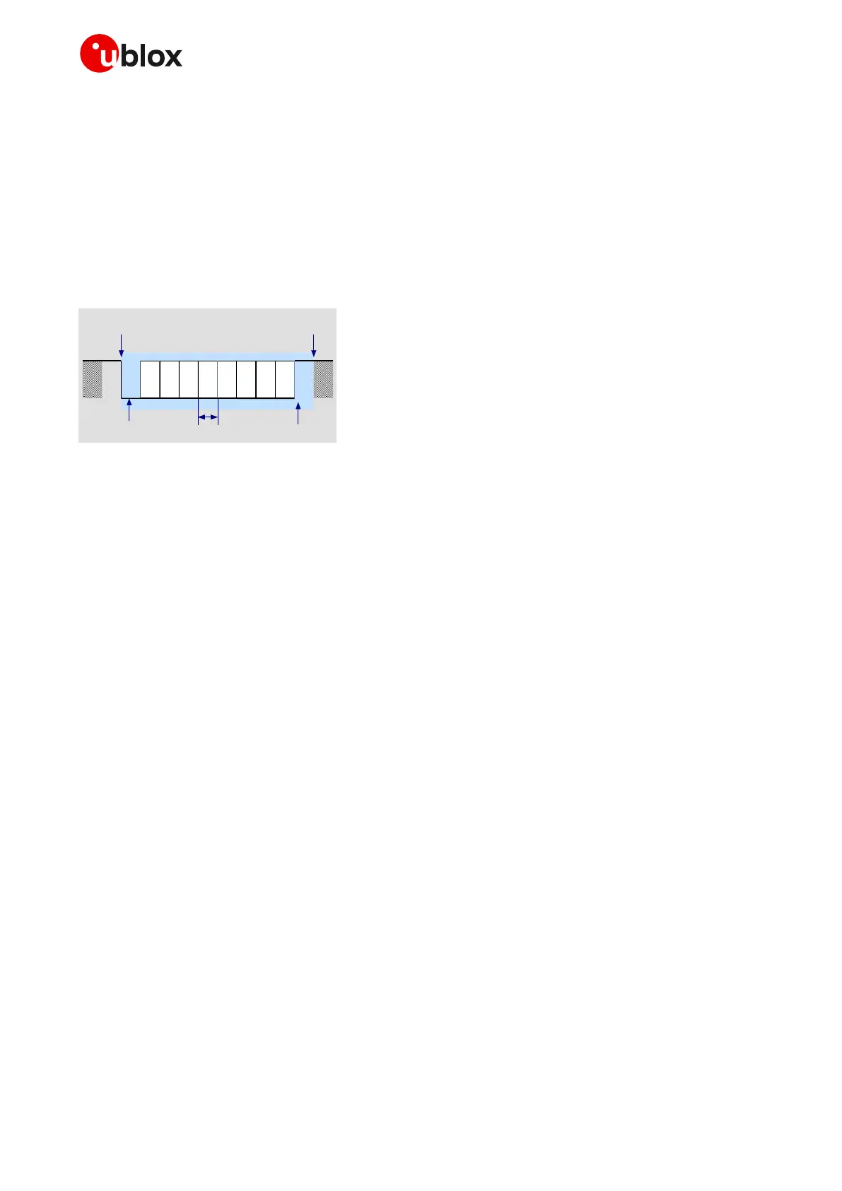
Figure 17 describes the 8N1 frame format.
Figure 17: Description of UART default frame format (8N1 = 8 data bits, no parity, 1 stop bit), with fixed baud rate
1.9.1.2 UART signals behavior
At the end of the module boot sequence (see Figure 12, Figure 13, Figure 14), the module is by default
in active mode, and the UART interface is initialized and enabled as AT commands interface.
The configuration and behavior of the UART signals after the boot sequence are described below:
• The module data output lines (RXD only if USIO variant 0 or 1 is set; RXD and DCD if USIO variant
2, 3 or 4 is set) are set by default to the OFF state (high level) at UART initialization. The module
holds these lines in the OFF state until the module transmits some data.
• The module data input lines (TXD only if USIO variant 0 or 1 is set; TXD and DTR if USIO variant 2,
3 or 4 is set) are assumed to be controlled by the external host once UART is initialized. The data
input lines have an internal active pull-up enabled.
1.9.1.3 UART and power saving
The power saving configuration is controlled by the AT+UPSV command (for the complete
description, see the SARA-R5 series AT commands manual [2]). When power saving is enabled, the
module automatically enters idle mode or deep-sleep mode whenever possible, and otherwise the
active mode is maintained by the module (see section 1.4 for definition and description of module
operating modes referred to in this section). The AT+UPSV command configures both the module
power saving and the UART behavior in relation to the power saving.
Four different power saving configurations can be set by the AT+UPSV command:
• AT+UPSV=0, power saving disabled: module forced on active mode and UART interface enabled
(default)
• AT+UPSV=1, power saving enabled: UART is cyclically enabled and module enters idle mode or
deep-sleep mode automatically whenever possible
• AT+UPSV=2, power saving enabled and controlled by the UART RTS input line (not supported if
HW flow control is enabled)
• AT+UPSV=3, power saving enabled and controlled by the UART DTR input line (not supported if
+USIO variant 2, 3 or 4 is set)
• AT+UPSV=4, power saving enabled and behavior equal to AT+UPSV=1

 Loading...


