SARA-R5 series - System integration manual
UBX-19041356 - R04 Design-in Page 62 of 118
C1-Public
2.4.2.3 Antenna trace design used for SARA-R5 series modules’ type approvals
The conformity assessment of u-blox SARA-R5 series LGA surface-mounted modules for regulatory
type approvals such as FCC United States, ISED Canada, RED Europe, etc. has been carried out with
the SARA-R5 series modules mounted on a u-blox host printed circuit board with a 50 grounded
coplanar waveguide designed on it, herein referenced as “antenna trace design”, implementing the
connection of the ANT LGA pad of the module, consisting in the cellular RF input/output of the
module, up to a dedicated 50 SMA female connector, consisting in the cellular RF input/output of
the host printed circuit board for external antenna and/or RF cable access.
☞ Manufacturers of mobile or fixed devices incorporating SARA-R5 series modules are authorized to
use the FCC United States Grants and ISED Canada Certificates of SARA-R5 series modules for
their own final host products if, as per FCC KDB 996369, the antenna trace design implemented
on the host PCB is electrically equivalent to the antenna trace design implemented on the u-blox
host PCB used for regulatory type approvals of SARA-R5 series modules, described in this section.
☞ In case of antenna trace design change, an FCC Class II Permissive Change and/or ISED Class IV
Permissive Change application is required to be filed by the grantee, or the host manufacturer can
take responsibility through the change in FCC ID and/or the ISES Multiple Listing (new application)
procedure followed by an FCC C2PC and/or ISED C4PC application.
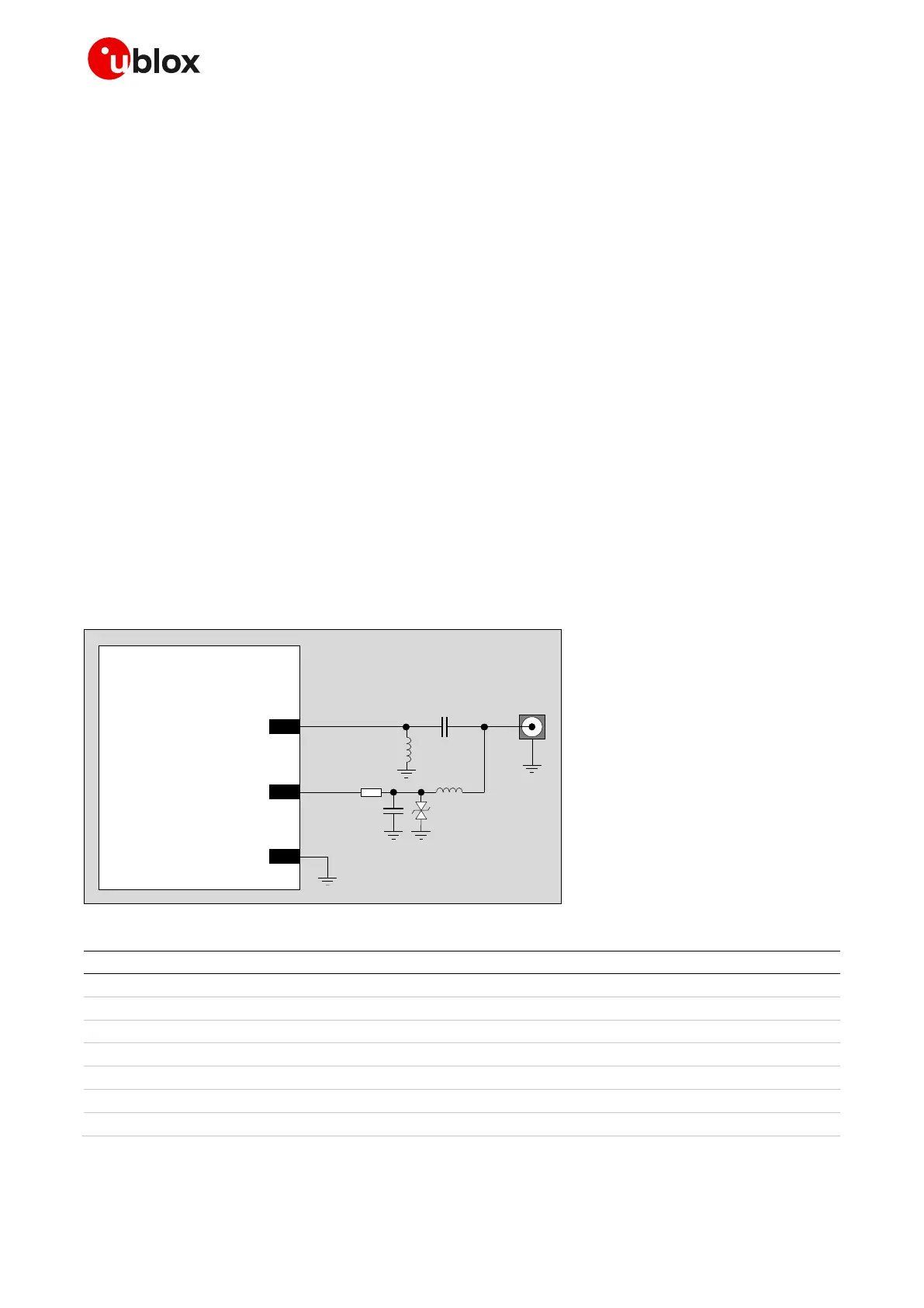
The antenna trace design is implemented on the u-blox host PCB as illustrated in Figure 37, using the
parts listed in Table 21, with the support of the additional optional antenna detection capability.
Guidelines to design a proper equivalent optional antenna detection circuit on a host printed circuit
board are available in section 2.4.5.

 Loading...


