SARA-R5 series - System integration manual
UBX-19041356 - R04 Design-in Page 82 of 118
C1-Public
Providing 1 UART with the TXD, RXD, RTS, CTS, DTR and RI lines only
☞ Compatible with USIO variants 0/1; not compatible with USIO variants 2/3/4 (see section 1.9.1.1).
If the functionality of the DSR and DCD lines is not required, or the lines are not available:
• Leave DSR and DCD lines of the module unconnected and floating
If RS-232 compatible signal levels are needed, two different external voltage translators (e.g. Maxim
MAX3237E and Texas Instruments SN74AVC4T774) can be used. The Texas Instruments chips
provide the translation from 1.8 V to 3.3 V, while the Maxim chip provides the translation from 3.3 V
to RS-232 compatible signal level.
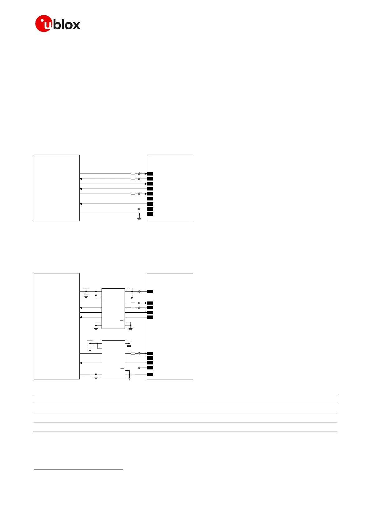
Figure 56 describes the circuit that should be implemented if a 1.8 V application processor (DTE) is
used, given that the DTE will behave correctly regardless of the DSR input setting.
Figure 56: 1 UART interface application circuit with 7-wire link in DTE/DCE serial communication (1.8 V DTE)
If a 3.0 V application processor (DTE) is used, then it is recommended to connect the 1.8 V UART
interface of the module (DCE) by means of appropriate unidirectional voltage translators using the
module V_INT output as 1.8 V supply for the voltage translators on the module side, as described in
Figure 57, given that the DTE will behave correctly regardless of the DSR input setting.

 Loading...


