SARA-R5 series - System integration manual
UBX-19041356 - R04 Design-in Page 83 of 118
C1-Public
☞ Provide accessible test points directly connected to TXD and RXD pins for FW update purpose and
to DCD and DTR pins for diagnostic purpose.
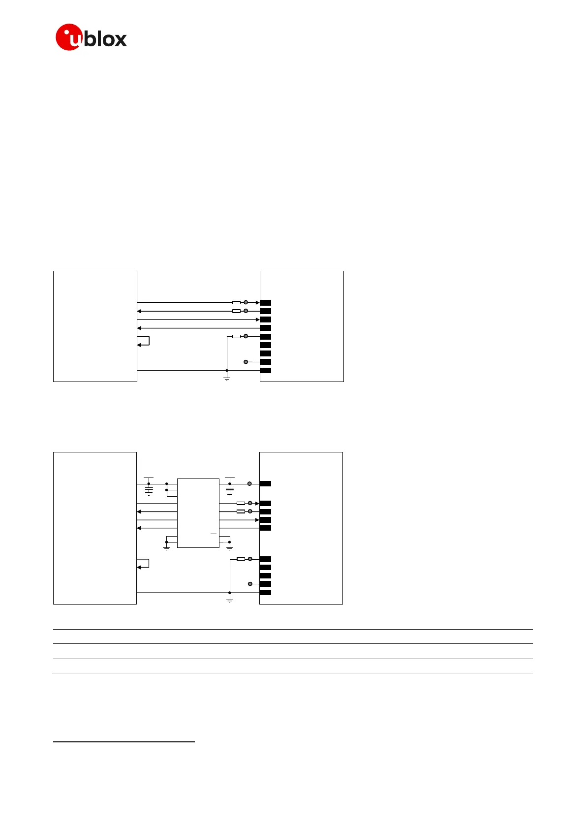
Providing 1 UART with the TXD, RXD, RTS and CTS lines only
☞ Compatible with USIO variants 0/1/3; not compatible with USIO variants 2/4 (see section 1.9.1.1).
If the functionality of the DSR, DCD, RI and DTR lines is not required, or the lines are not available:
• Connect the DTR input to GND, as useful to have the greeting text presented over the UART
• Leave DSR, DCD, and RI lines of the module floating
If RS-232 compatible signal levels are needed, the Maxim MAX13234E voltage level translator can be
used. This chip translates voltage levels from 1.8 V (module side) to the RS-232 standard.
If a 1.8 V application processor is used, the circuit should be implemented as described in Figure 58.
Figure 58: 1 UART interface application circuit with 5-wire link in DTE/DCE serial communication (1.8V DTE)
If a 3.0 V application processor (DTE) is used, then it is recommended to connect the 1.8 V UART
interface of the module (DCE) by means of an appropriate unidirectional voltage translator using the
module V_INT output as 1.8 V supply for the voltage translator on the module side, as in Figure 59.
Table 38: Components for 1 UART application circuit with 5-wire link in DTE/DCE serial communication (3.0 V DTE)
☞ Provide accessible test points directly connected to TXD and RXD pins for FW update purpose and
to DCD and DTR pins for diagnostic purpose.

 Loading...


