15
4.4.
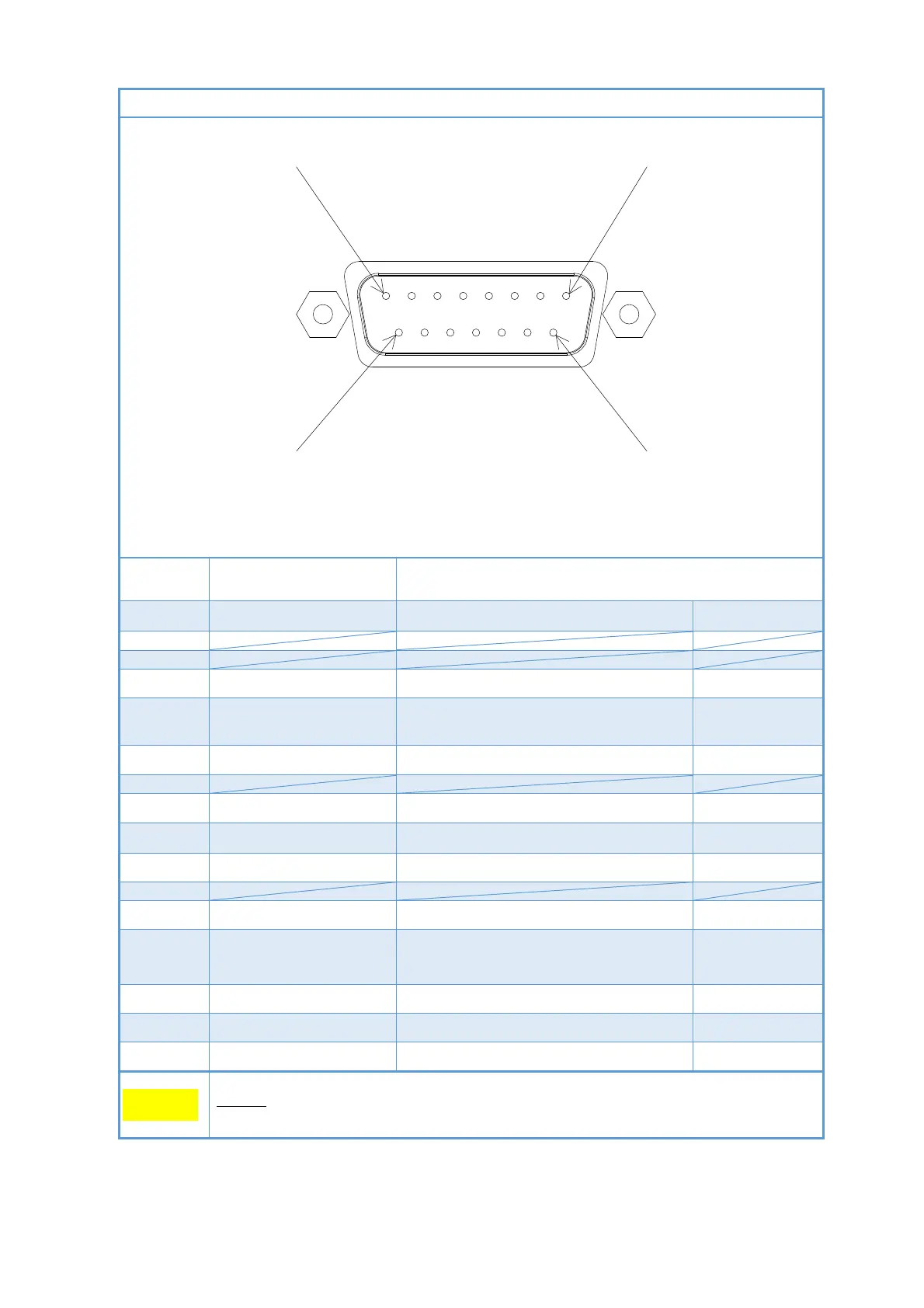
I/O connector serial communication type ST200-R
Fig. 4-4 Serial communication type ST200-R I/O connector pin layout
(D-sub15 pin(male), M2.6 screw)
1 Power supply Power supply for driving this unit (DC20V to 28V)
2
3
4 RS232C RxD RxD of RS-232C
5
Terminating resistor
for RS485
Terminating resistor for RS-485.
It is connected to pin13.
6 RS232C TxD TxD of RS-232C
7
8 Measured value output It outputs a pressure signal. (DC0V to 10V)
9 Power supply GND Ground for the power supply
10 RS485- Minus of RS-485
11
12 RS485+ Plus of RS-485
13
RS485+
(For connecting the
terminating resistor)
Terminating resistor for RS-485.
It is connected to pin5.
14 RS232C GND Ground for RS-232C
15 Signal GND Ground for the output signal
Case Frame ground Ground for frame
The shaded pins are used in the internal circuit, so do not wire them.
 Loading...