30 31
Of which: n is the transformer ratio coefficient between secondary and primary coil.
IX Ground Resistance Measurement Method
1 Multi-point Ground System
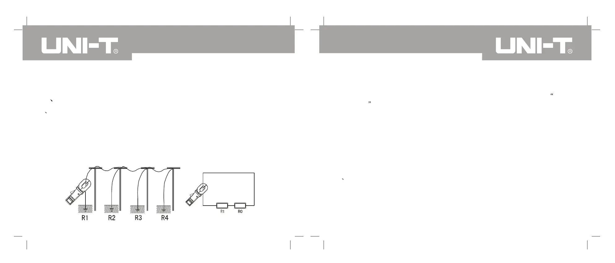
Multi-point ground system (ex. Electricity Transmission System tower grounding,
communication cables grounding system, some buildings etc.) are connected by
the overhead ground wires and form into the ground system. As shown in the
following picture, when measuring by the clamp meter, the equivalent circuit shall
be shown as follows:
Of which, R1 is the estimated ground resistance and R0 is the equivalent
resistance of all other towers ground resistance in parallel.
From the aspect of strict ground theory , as the existence of the so called mutual
resistance , R0, in general electrical engineering meaning, is not the parallel
value (slightly bigger than that of general electrical engineering meaning), but
ground hemisphere of each tower is much smaller than the distance between
towers and the great number of ground points, R0 is much smaller than R1. Thus,
it is reasonable to speculate R0=0 from the engineering aspect and the resistance
we measured should be R1.
After many comparison tests between tests under different environment,
occasions and traditional ways, the above speculation is fully reasonable.
2 Limited Point Ground System
The circumstance is quite common, for instance, some towers are connected with
each other by the over head ground wire; and some building's ground is not an
independent ground net but several ground bodies connected with each other by
wires.
Under this circumstance, regarding R0 in the above picture as 0 shall result in
UT276A/278A OPERATING MANUALUT276A/278A OPERATING MANUAL