20
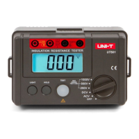
Model UT511: OPERATING MANUAL
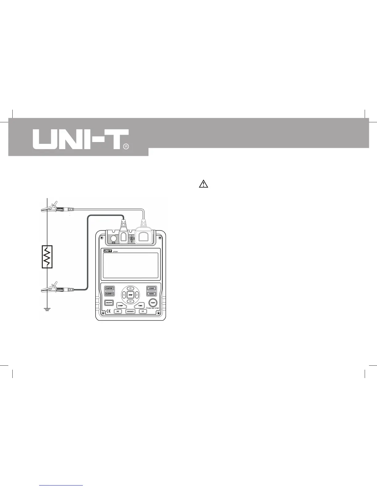
C. Low Resistance Measurement
Figure 6. Low Resistance Measurement
Caution
l When performing insulation resistance tests,
remove all power from the circuit to be measured
and discharge all the power.
To measure low resistance, set up the Meter as Figure
6 and do the following:
Press LO button to select low resistance
measurement..
Insert the red test lead into the LINE terminal and
the black test lead into EARTH terminal.
Connect the red and black alligator clip to the circuit
to be measured. When the resistance is less than
30 the buzzer sounds.
This range can test LED diode. Connect the anode
LED diode to the red test lead, the LED diode will
light up if it is good. If the LED diode does not light
up, it means it is damaged.
1.
2.
3.
4.
Red
Black