23
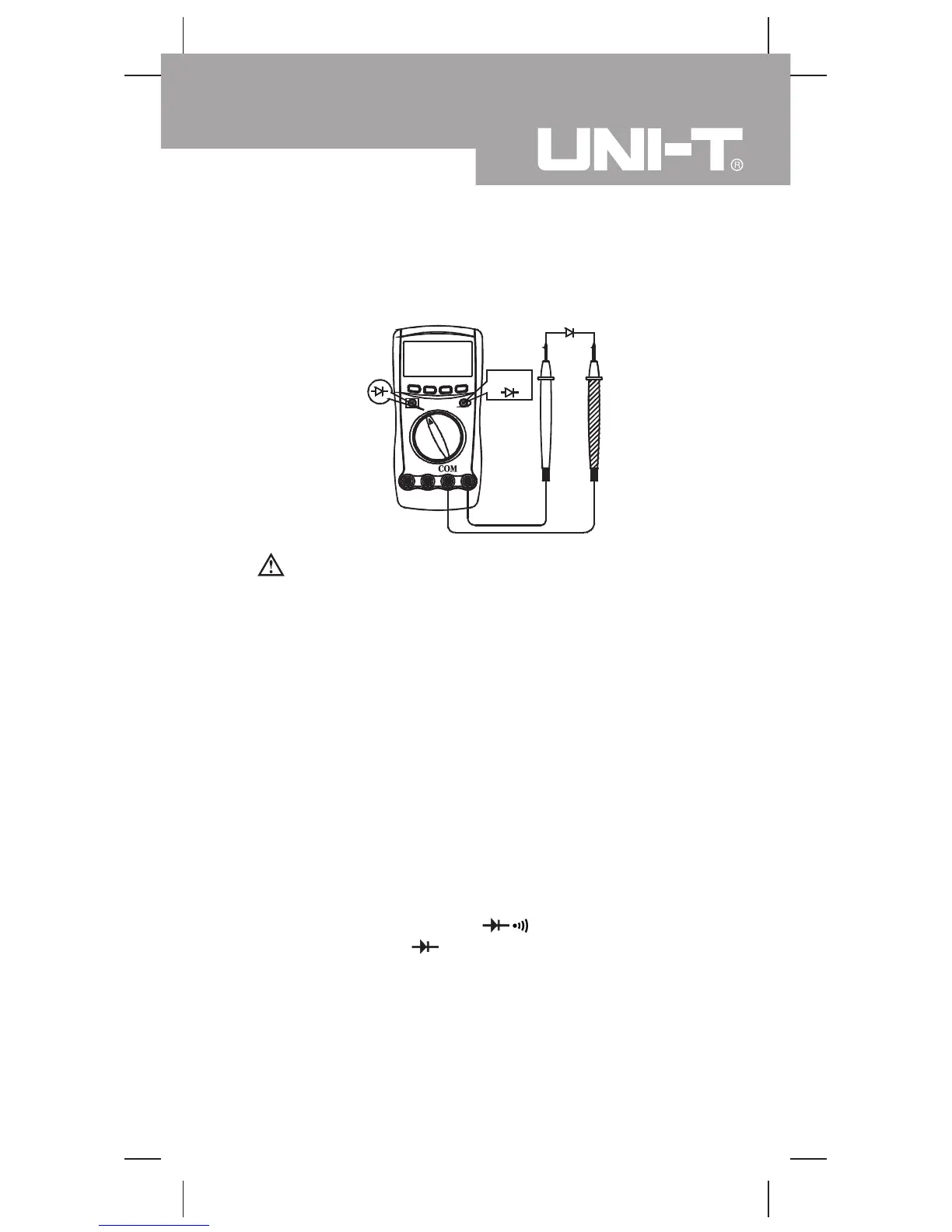
E.Testing Diodes (see figure 7)
Select
red black
( figure 7)
Warning
To avoid harms to you, please do not attempt to
measure voltages higher than 60V DC or 30V rms AC.
To avoid damages to the Meter or to the devices
under test, disconnect circuit power and discharge
all the high-voltage capacitors before testing diodes.
Use the diode test to check diodes, transistors, and other
semiconductor devices. The diode test sends a current
through the semicondutor junction, then measure the
voltage drop across the junction. A good silicon junction
drops between 0.5V and 0.8V
To test the diode out of a circuit, connect the Meter as
follows:
1. Insert the red test lead into the HzVΩ terminal and
the black test lead into the COM terminal.
2. Set the rotary switch toΩ and press BLUE
button to select measurement mode.
3. For forward voltage drop readings on any
semiconductor component, place the red test lead
on the component’s anode and place the black test
lead on the component’s cathode. The red test lead
polarity is “+” while the black test lead polarity is “-” .
Measurement Operation(7)
Model UT60F/G: OPERATING MANUAL