UTD1000 User Manual
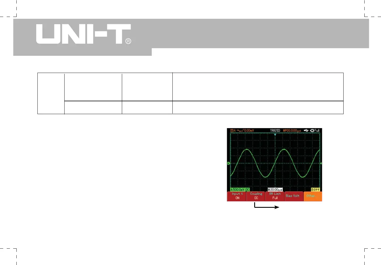
Figure 2-6 Both DC and AC quantities
of the signal are displayed
DC coupling setup
Others
Probe
Polarity
1X
10X
100X
1000X
Normal
Invert
Select one of the values based on the probe attenuation factor
to keep the reading of the signal being measured correct.
Normal waveform display Waveform is invert
Table 2-1 Explanatory notes for channel A menu(continued)
1. Setting channel coupling
Take the example of applying a signal to Channel A.
The signal being tested is a sine signal that contains DC
quantities. Press [A] to select Channel A. Then press
[F1] to set A input to “ON”. Next press [F2] to select DC
coupling. Both DC and AC quantities of the signal being
tested and input to Channel A can pass through. The
waveform display is as follows :
 Loading...