UTD2000 Series User Manual
15
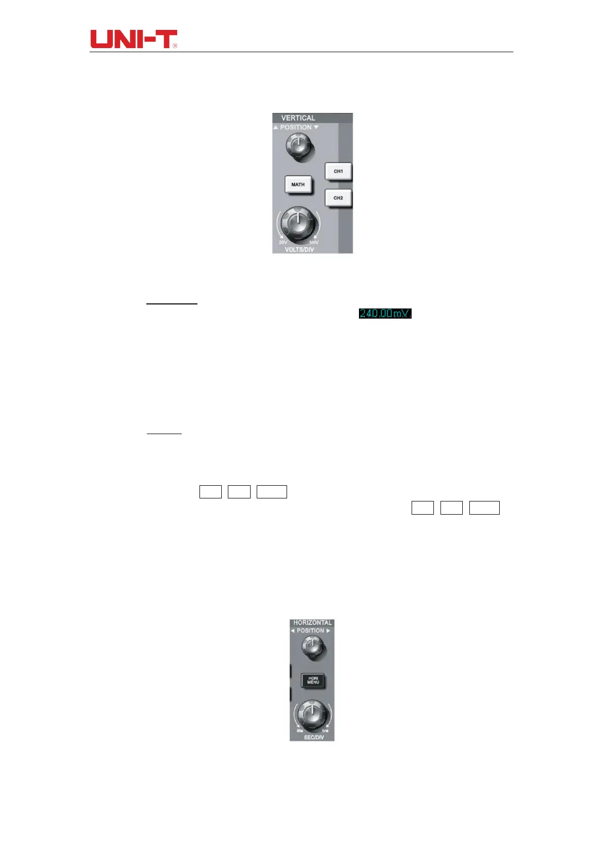
control area. Practices below will gradually guide you to get familiar with the controlling of
the vertical system.
Figure 1-6 Vertical Control Area on the Panel
(1) Vertical POSITION: vertical position knob, user can change the current vertical position
of channel waveform, the vertical position value will display on the
baseline cursor area. Press this knob to get the dispayed channel position back to the
vertical center.
If the coupling mode of channel is DC, user can fast measure the DC component
of signal by observing the difference between waveform and signal ground.
If the coupling mode of channel is AC, the DC component in the signal will be
filtered, which helps to display AC component of signal with higher sensitivity.
(2) Vertical SCALE: Change vertical setting and observe the change of status information.
User can confirm any change of vertical scale level by the information displayed on the
status bar. Rotate the vertical scale knob to change the vertical scale level of
“VOLTS/DIV”, and then the scale level of channel on the stauts bar will be changed
accordingly. Press CH1, CH2, MATH to display operation menu, symbols, waveform
and scale level status of corresponding channels. Double click CH1, CH2, MATH to
turn off the channel.
1.6 Introduction to the Horizontal System
As shown in the figure below, there is one key and two knobs within the horizontal control
area. Practices below will gradually guide you get familiar with the setting of horizontal time
base.
Figure 1-7 Horizontal Control Area on the Panel