20
3.6 - FLUE GAS EXHAUST PIPE CONNECTION
To connect the ue gas exhaust pipe, local and national stand-
ards must be observed
ATTENTION:
The chimney must comply
with the standards in force.
HEAD AVAILABLE AT THE BASE OF THE CHIMNEY
D (Drain) + I (Intake)
∆p = 100 Pa
The maximum permitted length of the pipes is determined
by head (∆p) available at the base of the chimney.
HEAD AVAILABLE AT THE BASE OF THE CHIMNEY
D (Drain) I (Intake)
∆p = 100 Pa
-
The maximum permitted length of the pipes is determined
by the head (∆p) available at the base of the chimney.
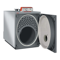
B23P
ATTENTION
For this type of connection, the room follows the
same installation rules for boilers with natural
draught.
Connection to a combustion products evacuation pipe outside
the room; the combustion air is taken directly from the room
where the appliance is installed.
C63
ATTENTION
For the C63 conguration, you must order
the optional air intake kit, which contains the
installation instructions.
Separate combustion air intake and combustion products
evacuation pipes. (Commercial accessories)
ATTENTION:
for B23P types of connection, the
room follows the same installation rules
for natural draught
boilers.
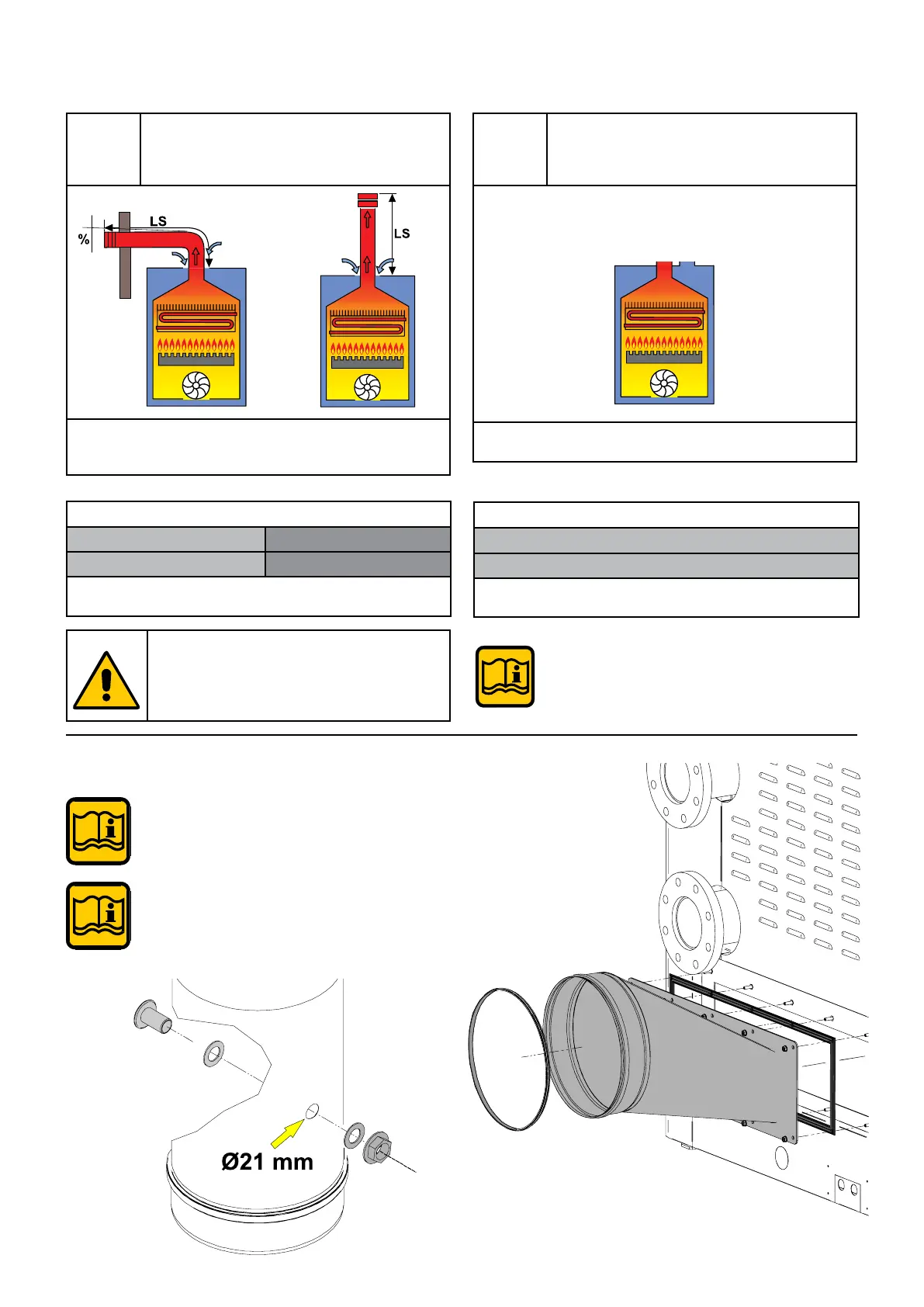
3.6.1- MANIFOLD CONNECTION
EXHAUST PIPE
Use the nuts and washers contained in the bag to
x the ue gas exhaust manifold.
The ue gas inlet must be positioned on the rst
straight section within 1 metre from the boiler.
To create the ue gas inspection inlet, make one
Ø 21 mm hole in the ue gas outlet pipe and t the
inspection inlet following the indicated sequence.
The boiler is type approved for the exhaust congurations listed
below: