39
Installation instructions
ENGLISH
INDICATIVE DIAGRAM, REFERRING TO BOILERS
MODULEX 150 ÷ 350
NOZZLES - PRESSURE - CAPACITY TABLE
MODULEX EXT: 440 - 550 - 660 - 770 - 900
Type of Gas Supply Press. Ø Noz-
zles
Fan
deector
Fan speed CO
2
levels Start.
power
[mbar] (mm) [Ø/mm] min FL max FU [%] [%]
min max IG
Nat. gas (G20) 20 9 NO 29 96 9.0 9.0 50
Nat. gas (G25) 25 9 NO 28 98 9.1 8.6 50
Nat. gas (G27) 20 9 YES 28 94 9.1 9.3 50
Propane (G31) 37 9 NO 28 90 10.2 10.4 50
MODULEX EXT: 348
Type of Gas Supply Press. Ø Noz-
zles
Fan
deector
Fan speed CO
2
levels Start.
power
[mbar] (mm) [Ø/mm] min max [%] [%]
min max IG
Nat. gas (G20) 20 9 NO 29 76 9.0 9.0 50
Nat. gas (G25) 25 9 NO 28 82 9.1 8.6 50
Nat. gas (G27) 20 9 YES 28 94 9.1 9.3 50
Propane (G31) 37 9 NO 28 73 10.2 10.4 50
Follow this procedure to also adjust the other modules.
If the capacity read is too low, make sure the power feed and
drain system (feed and drain pipes) are not clogged.
If they are not clogged, make sure the burner and/or heat ex-
changer is not dirty.
C) CONCLUSION OF THE BASIC
CALIBRATIONS
- Check the CO2 values at minimum and maximum levels.
- If necessary, make any adjustments.
For proper operation, the CO
2
values must be
calibrated with particular attention, observing
the values indicated in the table.
NOTE: Do not force the end stroke limits
of the adjustment screw.
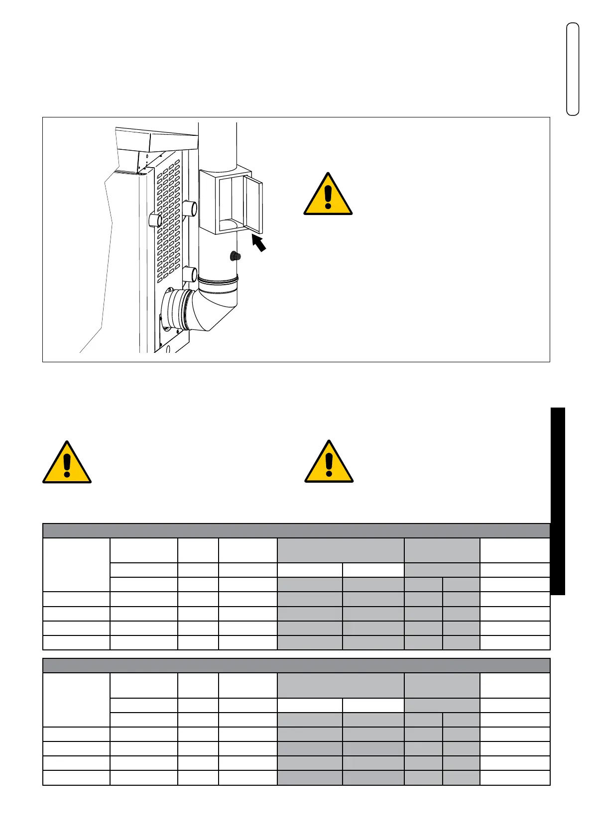
ATTENTION
To calibrate the VG (Gas Valves) in the
boiler room, follow the procedures below.
The VG must be calibrated
with chimney pressure = 0 Pa;
for this reason:
- open the smoke duct 1 inspection door,
after calibration, restore the door gasket.
- Close the ue gas inspection inlet (1) with the specic cap
(2 - 3)