Do you have a question about the Uniden 2020 and is the answer not in the manual?
Procedure for adjusting the noise blanker circuit.
Procedure for adjusting the marker oscillator.
Step-by-step guide for ALC meter adjustment.
Procedure for tuning receiver RF coils.
Procedure for aligning IF tuning coils.
Procedure for adjusting coils in the IF unit.
Procedure for adjusting carrier balance in the IF unit.
Procedure for adjusting the RF output meter.
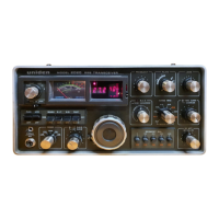
This document outlines the alignment procedures and technical specifications for the Uniden 2020, a device that appears to be a transceiver or a similar radio communication unit, given the references to RF, IF, transmitter, receiver, and various frequency bands. The manual provides detailed instructions for adjusting different circuits and measuring voltages, indicating a focus on precise calibration and maintenance.
The Uniden 2020 is a radio communication device that includes both receiver and transmitter functionalities, along with various auxiliary circuits for signal processing and control. Key functional blocks include:
While specific numerical specifications like power output or sensitivity are not explicitly listed in the provided excerpts, the document details various frequencies and voltage levels that are critical for the device's operation and alignment.
The manual primarily focuses on alignment and maintenance, but it implicitly reveals several usage features:
The document is essentially a maintenance guide, detailing precise steps for alignment and troubleshooting. Key maintenance aspects include:
In summary, the Uniden 2020 is a sophisticated radio transceiver requiring meticulous alignment and maintenance. The provided manual serves as a comprehensive guide for technicians, ensuring the device operates within its specified parameters for optimal performance.
| Brand | Uniden |
|---|---|
| Model | 2020 |
| Category | Transceiver |
| Language | English |