Page 31
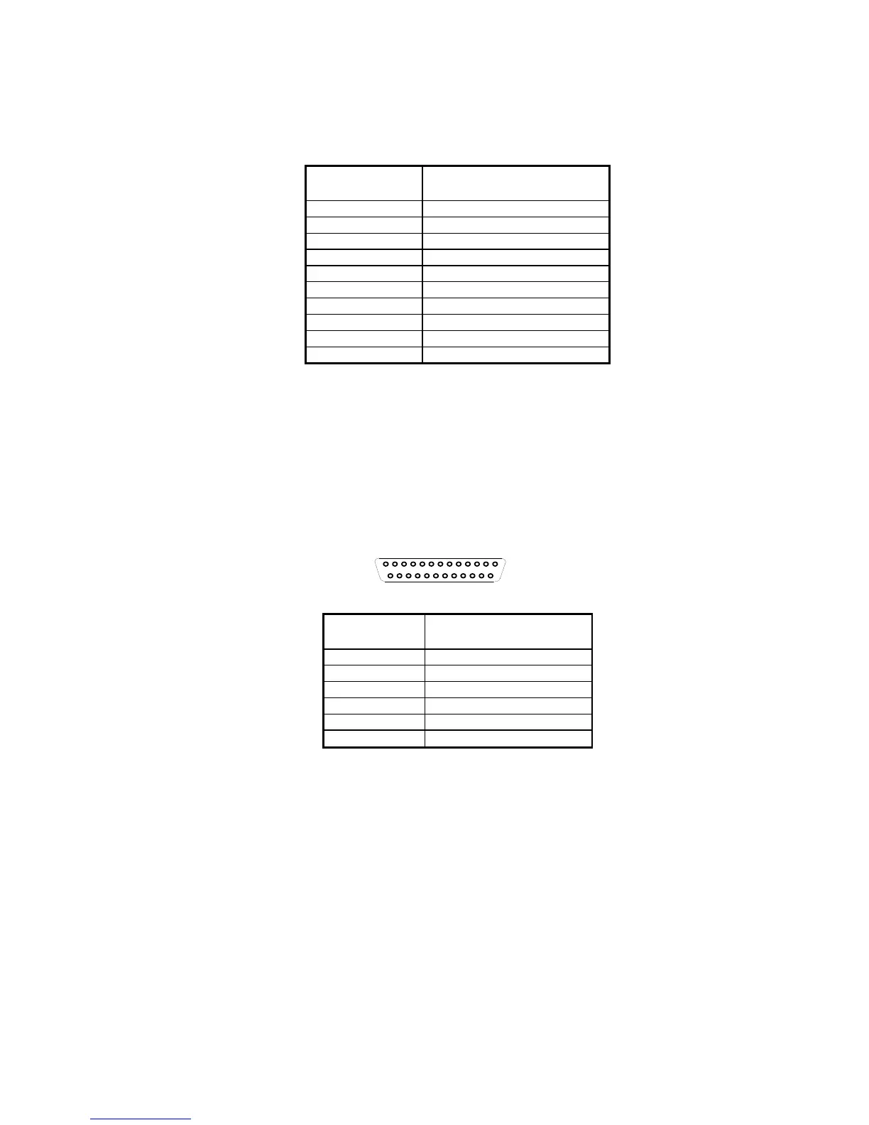
TTL RS232 Interface:
The following table shows pinout for TTL RS232 interface at modular
connector:
Pin
Number
Signal
1 Not Used
2 VCC (+5V, output)
3 DET
4 GND
5 RXD
6 TXD
7 Power Input (+5V)
8 CTS
9 RTS
10 Not Used
Note:
(1) DET signal is bi-directional I/O pin and for internal use only.
(2) CTS and RXD are input signals and take 0V to 5V only. If the
scanner is used to interface with a standard RS232 port, those
signals should not be connected.
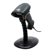
Standard RS232 Interface:
To support standard RS232 interface, an RS232 adapter cable from the
manufacture must be used. This cable is a special one and cannot be
replaced by the others. One end of that cable which has RS232 signal
presented is a DB25 or DB9 female connector and has following pinout:
DB25 Female (Front View)
1
13
14
25
Pin
Number
Signal
2 RXD
3 TXD
14 CTS
16 RTS
7 GND
25
Power Input (+5V
±5%)